



How Do You Select Filter Media for High-Humidity Coastal Sites?
Select filter media for high-humidity coastal sites by matching the complete media construction to three conditions: airborne salt, liquid-water exposure, and the pressure-drop limit of the equipment. A suitable construction must retain its required particle efficiency after humid exposure, resist deformation when wet, and tolerate repeated wetting and drying. Initial dry efficiency and a water-repellent surface are useful screening properties, but neither establishes coastal suitability.
Start by distinguishing humid air from fog, wind-driven spray, and condensation. These exposures create different failure mechanisms. Where liquid water reaches the intake, media selection must be coordinated with droplet separation and drainage. Otherwise, even a mechanically strong, hydrophobic filter can experience blocked pores, salt penetration, or rapid pressure-drop growth.
Identify what reaches the filter surface
Relative humidity describes the air, while condensation depends on the relationship between air moisture and surface temperature. A filter housing or media surface below the local dew point can collect liquid water even when rain and spray never enter the intake. Operating records should therefore include temperature and humidity near the filter, shutdown conditions, and evidence of overnight condensation.
Salt adds another complication. Deposited sea salt absorbs moisture as humidity rises, forming concentrated liquid at conditions governed by its composition. A filter that appears dry during inspection can hold damp salt deposits during operation. As humidity falls, the deposits recrystallize. Repeated cycles redistribute material within the media and change airflow resistance.
Also establish the contamination that matters downstream. A particle-efficiency result does not, by itself, describe protection against salt transported in liquid water. Where corrosion or conductive deposits are concerns, salt penetration and liquid carryover deserve separate evaluation.
Choose the media structure around wet performance
Fully synthetic media are a useful starting point where wet strength and low fiber moisture absorption matter. However, the fiber name alone is insufficient. Fiber diameter distribution, pore structure, basis weight, bonding, and supporting layers determine how the sheet captures particles and survives service.
A depth-oriented structure spreads captured material through its thickness, which can delay resistance growth under suitable dust conditions. A fine surface layer improves capture near the upstream face, but a concentrated deposit there can become restrictive when wetted. Graded constructions combine a more open upstream region with finer capture downstream. Their benefit must be demonstrated with the actual contaminant mix; fine salt aerosol and coarse mineral dust do not load a filter in the same way.
Hydrophobic treatment reduces surface wetting and can help resist liquid entry. It does not stop water vapor from reaching deposited salt. Nor does it guarantee drainage from narrow pleat channels. Assess water repellency alongside liquid penetration resistance, airflow resistance, and performance after loading. A clean-sheet droplet demonstration says little about a dust-covered filter after extended coastal exposure.
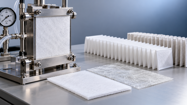
Membrane composites offer another route to fine-particle capture and resistance to liquid penetration. Their suitability depends on membrane integrity, support structure, lamination quality, and available filtration area. A restrictive membrane or poorly supported laminate can consume too much of the pressure budget or suffer damage during pleating.
Separate mechanical capture from electrostatic contribution
Some meltblown media use electrostatic charge to achieve high initial efficiency at relatively low resistance. That contribution should be understood before comparing products. Humidity alone does not establish how a particular electret will behave; charge stability also depends on polymer formulation, charging process, temperature, and exposure to contaminants such as oily aerosols.
Request particle-size efficiency data after conditioning appropriate to the application, with the conditioning method clearly identified. Compare initial performance with the conditioned result and confirm that the remaining efficiency meets the equipment requirement. This prevents a low initial pressure drop from masking insufficient capture when the electrostatic contribution diminishes.
How much can nano meltblown media improve dust holding capacity?
There is no defensible universal improvement percentage. “Nano meltblown” does not define a consistent fiber diameter distribution, layer thickness, pore structure, or test method. A finer-fiber layer can increase capture efficiency, but dust holding capacity is the mass retained before a defined endpoint, commonly a terminal pressure drop. Higher efficiency alone does not prove greater capacity.
The improvement is credible when the construction maintains useful pore volume, distributes deposits effectively, and reaches the specified final resistance after retaining more contaminant. A dense fine-fiber layer can instead load rapidly at the surface. Under humid salt exposure, liquid bridging between fibers and deposits can further accelerate resistance growth.
A meaningful comparison requires the same face velocity, exposed area, challenge material, humidity sequence, and terminal pressure drop. Initial and loaded particle efficiencies must also be reported. For complete filter elements, use comparable dimensions and installation conditions, and disclose differences in media area. Otherwise, extra pleated area can be mistaken for a benefit from the fiber technology.
Calculate relative capacity improvement as the difference between candidate and reference retained masses divided by the reference retained mass, expressed as a percentage. Keep that result attached to its test conditions. A gain measured with dry laboratory dust does not establish an equivalent gain with coastal salt, fog, or mixed contamination.
Test the laminate and pleated element, not just the flat sheet
Coastal durability depends on the interfaces within the filter. Adhesive bonds, support layers, pleat stabilizers, edge seals, and gaskets all experience the same moisture cycles as the filtration layer. A robust sheet can still fail if a laminate separates or an edge seal opens.
Bonding processes introduce their own tradeoffs. Excessive adhesive coverage reduces open area and raises resistance. Insufficient bonding allows layers to move or separate under airflow and moisture exposure. Evaluate the finished laminate for peel integrity after humid aging and wetting, with particular attention to folds and other highly stressed regions.
Pleat spacing affects both airflow and water behavior. Closely packed pleats provide more nominal area, but wet deposits and narrow channels can obstruct access to that area. Deformation under differential pressure creates additional restrictions. Inspect pleat shape after humid loading and verify that supports maintain spacing at the intended final resistance.
For pulse-cleaned elements, include repeated cleaning cycles in the evaluation. A surface that releases dry dust effectively may retain a damp salt-and-dust layer. Cleaning pulses also impose mechanical stress on wet media and bonded interfaces. Results from a static, unpleated sample cannot establish suitability for that duty.
Use a test sequence that exposes coastal failure mechanisms
Begin with the actual operating airflow, allowable pressure drop, required particle efficiency, and exposure profile. Then compare candidate constructions through a sequence that includes clean performance, representative loading, humid exposure, and recovery after drying. This reveals whether resistance rises temporarily with moisture or remains elevated because deposits have compacted or migrated.
- Establish the clean baseline. Measure resistance and particle-size efficiency at the intended face velocity. Record media area and construction so later differences have an identifiable cause.
- Introduce contamination representative of the site. Where mineral dust and salt both matter, their loading sequence should reflect the expected exposure rather than treating either material as a complete substitute.
- Include humid holds and wetting events where relevant. Track pressure drop during exposure and after drying. Repeated cycles reveal behavior that a single humidity exposure misses.
- Inspect the assembled element for pleat collapse, delamination, seal leakage, and downstream deposits. Distinguish penetration through intact media from bypass around the element.
For salt-loading trials, distinguish dry retained salt from absorbed water. Weighing a damp sample without a defined conditioning procedure can make moisture uptake appear to be additional contaminant capacity. The reported mass basis should be consistent across candidates.
Interpret pressure and efficiency together. A stable pressure drop accompanied by increasing downstream penetration is not evidence of good service life. Conversely, a temporary resistance increase during fog exposure has a different implication from permanent restriction after drying. Both affect selection, but they point to different changes in media structure or intake design.
Resolve water management before accepting a higher-grade medium
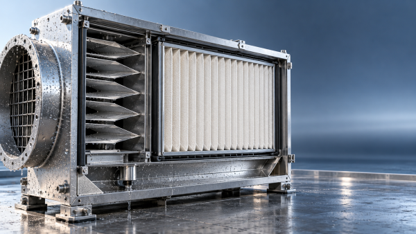
When free water regularly reaches the final filter, review the intake arrangement. Weather protection, droplet separators, drainage paths, and filter orientation determine how much liquid the media must handle. Separator performance depends on droplet size and airflow; effective removal of large spray droplets does not establish equal removal of fine fog.
Drainage needs a continuous discharge path. Water trapped against a filter edge or in a housing pocket can be drawn downstream or repeatedly wet the same section. A more water-repellent medium will not correct standing water caused by poor housing geometry.
Use the location of downstream contamination to guide investigation. Deposits concentrated near a gasket suggest bypass, while deposits spread across the downstream face warrant examination of penetration or carryover through the media. These patterns are diagnostic clues; confirm the cause with inspection and testing before changing the filtration layer.
Write the specification around measurable acceptance conditions
A useful specification identifies the required efficiency, operating airflow, clean and final resistance limits, relevant humidity and wetting exposures, and acceptable physical condition after testing. Include the complete element construction and test conditions. Terms such as “coastal grade,” “water resistant,” or “nano” are too broad to serve as acceptance criteria on their own.
Compare lifecycle cost only after candidates meet those conditions. Use the resistance curve over loading, replacement frequency under comparable exposure, and any required prefiltration. The lowest clean resistance does not necessarily produce the lowest operating cost if humid deposits cause rapid restriction.
During initial service, record differential pressure alongside airflow, humidity, fog events, and shutdown periods. Normalize comparisons for airflow changes. These records establish whether the selected construction behaves as predicted and provide a defensible basis for adjusting replacement intervals or revising the intake arrangement.
Recommendation
 Oct 20, 2026
How Do You Select Filter Media for High-Humidity Coastal Sites?
How much can nano meltblown media improve dust holding capacity? Discover how to select coastal filter media that withstand humidity, manage salt exposure, and control pressure drop.- Oct 20, 2026
How Can Suppliers Demonstrate Air Filter Media Batch Consistency?
Qualify high humidity filter media for coastal sites with confidence. Learn how traceability, representative sampling, and humidity testing verify batch consistency before you buy. - Oct 20, 2026
How Do You Qualify Alternatives to Glass Fiber Filter Media?
Ensure air filter media batch consistency when replacing glass fiber. Discover qualification tests, production checks, and supplier controls to reduce risk and choose with confidence.