



When can nanofiber filter media lower pressure drop in fine filtration?
When Can Nanofiber Filter Media Lower Pressure Drop in Fine Filtration?
Fine filtration is often treated as a simple trade-off: capture smaller particles and pressure drop rises. In practice, that is only partly true. A well-designed nanofiber layer can reduce initial airflow resistance compared with a conventional fine-fiber structure targeting similar particle capture, but only under specific structural and processing conditions.
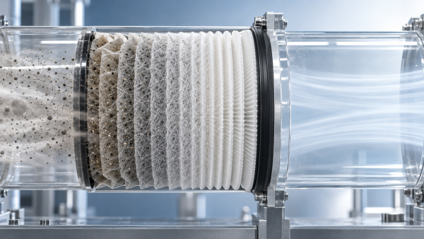
The reason is not that nanofibers somehow “ignore” the physics of airflow. Their value comes from how they are deployed. A very thin, highly porous nanofiber web can create an efficient interception layer at the surface of a more open substrate. Instead of forcing air through a thick, densely loaded depth medium, the filter can separate particles near the upstream face while preserving comparatively open flow channels beneath it.
For technical evaluation teams, the important question is therefore not whether Nanofiber Filter Media is inherently low-resistance. It is whether the complete media construction—nanofiber layer, support substrate, bonding system, pleating behavior, and expected dust-loading profile—delivers lower pressure drop at the required filtration level in the actual equipment.
The condition: a thin selective layer must replace bulk resistance
A nanofiber layer is most likely to lower pressure drop when it replaces part of a denser or thicker fine-filtration structure rather than being added on top of an already restrictive substrate. This distinction is easy to miss during early material selection.
Traditional fine filtration media often relies heavily on depth loading. Particle capture occurs throughout a relatively thick web, which can provide good dust-holding capacity but may require a tighter fiber network to reach the target efficiency. A nanofiber coating or web, by contrast, can concentrate fine-particle capture near the surface. If the nanofiber basis weight is controlled carefully, the underlying base media can remain more open than it would in a conventional all-fine-fiber design.
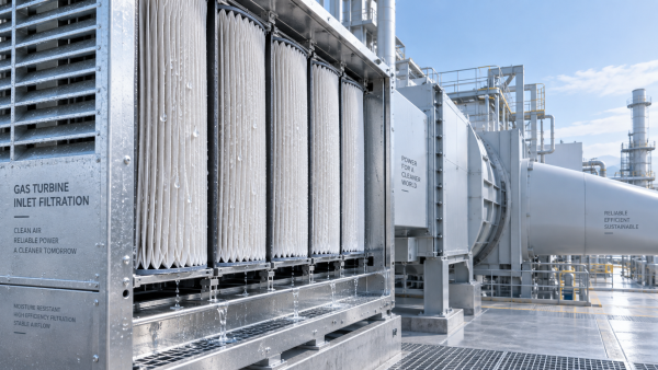
This is especially relevant where a filter must remove fine dust while maintaining adequate airflow through a limited filter area. Automotive air intake systems, turbine inlet filtration, industrial dust collection, electronic manufacturing environments, and certain clean-process applications all present versions of this constraint. The operating conditions differ, but the design tension is familiar: high capture efficiency is necessary, while fan energy, available static pressure, noise, and equipment duty must remain within acceptable limits.
The favorable situation is usually a “surface efficiency” design: a low-basis-weight nanofiber layer creates the needed fine-particle capture, while the substrate provides mechanical integrity, pleat support, and a relatively low-resistance air pathway. If the nanofiber layer becomes too heavy, too compact, or poorly distributed, it stops functioning as a selective surface layer and becomes another airflow bottleneck.
Why smaller fibers do not automatically mean higher resistance
At first glance, smaller fiber diameter appears likely to increase pressure drop. Smaller fibers create more available surface area and more opportunities for particle capture, but they also increase the number of fiber-air interactions. If all other variables remain unchanged, reducing fiber diameter can indeed raise resistance.
The practical advantage of nanofibers comes from changing several variables at once. Because nanofibers are effective at capturing fine particles, only a very small mass of material may be required. The resulting layer can be extremely thin and retain high porosity. In that configuration, the increase in local fiber surface area may be offset by the short flow path and the open structure of the layer.
This is why fiber diameter alone is not a useful purchasing or engineering criterion. Two media samples may both be described as nanofiber-based, yet behave very differently. One may have a light, uniform web with open pores and low initial resistance. The other may contain fiber bundles, dense zones, blocked pores, or excessive add-on weight. Their nominal material category is the same; their airflow behavior is not.
For evaluators, the more meaningful variables are the relationship between fiber diameter, layer thickness, basis weight, porosity, pore-size distribution, and air permeability. These must be examined as a system. A single low pressure-drop result at one face velocity is useful, but it should not substitute for understanding how the media was constructed.
The substrate often decides whether the design works
Nanofiber performance is frequently discussed as though the nanofiber layer acts alone. In finished filter media, that is rarely the case. The substrate has a major influence on initial pressure drop, mechanical stability, pleatability, burst resistance, humidity response, and the consistency of the coating process.
An overly dense substrate can erase much of the airflow benefit created by a thin nanofiber web. Conversely, a substrate that is too open may not support the nanofiber layer adequately during pleating, pulse cleaning, handling, or exposure to vibration. It may also allow the functional layer to deform under differential pressure. A good design is not simply “the most breathable backing.” It is the backing that preserves a controlled pore structure after conversion into a filter element.
This is where materials manufacturing capability matters. Fully synthetic wet-laid substrates can offer a route to tailored mechanical properties and controlled fiber distribution. Lamination methods also matter because adhesive choice and application method can close pores or create localized resistance. PUR lamination, hot-melt adhesive lamination, solvent-based emulsion spray lamination, and ultrasonic lamination each create different bonding patterns and thermal histories. The appropriate process depends on the polymer system, substrate sensitivity, intended service temperature, and required bond strength.
Hangzhou Chaocai Materials Co., Ltd. works across these manufacturing platforms while developing functional advanced materials for demanding filtration applications. That kind of process breadth is relevant because filtration media performance does not end with polymer formulation. The same nanofiber chemistry can produce different results when paired with a different base material or joined through a different lamination route.
Initial pressure drop is only the first checkpoint
A media sample may show an attractive initial pressure drop in laboratory testing and still disappoint in service. Fine filtration performance changes as dust accumulates, and the loading pattern is often more important than the clean-state number.
Nanofiber layers tend to promote surface loading. That can be beneficial because particles are retained near the upstream face instead of penetrating deeply into the substrate. In applications using pulse-jet cleaning, this surface-oriented structure may support more effective dust release than a depth-loaded medium, provided the nanofiber layer has sufficient adhesion and flex durability.
But surface loading can also produce a rapid rise in differential pressure when the challenge dust is sticky, oily, hygroscopic, or highly compactable. Fine soot, oil mist, resinous aerosols, high-humidity dust, and certain process powders do not behave like dry test dust. They can form a dense cake that dominates system resistance regardless of how low the initial media pressure drop was.
For that reason, a lower clean pressure drop should not be translated directly into lower lifecycle energy consumption or longer filter life. The claim becomes credible only when the expected contaminant, airflow cycle, cleaning method, temperature, humidity, and replacement threshold have been considered. In critical systems, it is worth comparing pressure-drop evolution over a representative loading cycle rather than comparing only one clean-media value.
Where nanofiber media is most likely to show a real advantage
Nanofiber Filter Media is generally most compelling when the system needs improved fine-particle capture but cannot accept a major increase in fan load or filter size. Several conditions tend to support its use:
- The filtration target requires fine-particle efficiency beyond what an open conventional substrate can provide on its own.
- The nanofiber layer can be applied as a thin, continuous, porous coating rather than as a heavy secondary web.
- The base media has adequate permeability but still provides enough stiffness and dimensional stability for downstream pleating and assembly.
- The dust is predominantly dry and the application benefits from near-surface particle capture.
- The end-use environment does not degrade the nanofiber polymer or weaken the bond between functional layer and substrate.
Gas turbine inlet systems illustrate the need for careful judgement. The benefit of low resistance is clear because pressure loss affects the entire air-handling system. Yet the media must also tolerate humidity changes, outdoor contaminant mixtures, mechanical vibration, and sometimes aggressive cleaning conditions. In automotive intake filtration, packaging constraints and pulsating airflow may be equally important. Semiconductor and biopharmaceutical process filtration demand a different level of contamination control, material compatibility, and process validation. A media design suitable for one of these environments should not be assumed suitable for another merely because the initial efficiency figures look comparable.
How to compare media without being misled
Pressure-drop comparisons only have value when the test conditions are aligned. A lower value measured at a lower face velocity, smaller effective filtration area, different humidity, or different preconditioning state does not establish a material advantage. Technical teams should ask for the full test context before ranking candidate media.
For general ventilation applications, ISO 16890 is commonly relevant because it evaluates filters in relation to particle size fractions and includes conditioning concepts that matter for some electret-based media. For high-efficiency particulate air and ultra-low penetration applications, EN 1822 and the related ISO 29463 series are commonly referenced. These standards serve different purposes and should not be treated as interchangeable. The applicable test method depends on the filter class and end-use requirement.
At the media-development stage, a disciplined comparison normally includes initial resistance at the same face velocity, fractional efficiency across the relevant particle range, thickness and basis weight, air permeability, tensile behavior, and resistance growth during loading. If the material will be pleated, the test plan should also consider whether pleating creates cracks, stretching, or local compression in the nanofiber layer. A web that looks uniform on a flat laboratory coupon may behave differently at the fold radius of a finished element.
Questions worth raising with a media supplier
- Is the stated pressure drop for the complete composite or only for the base substrate?
- What face velocity, airflow direction, sample area, and conditioning procedure were used?
- How is nanofiber basis weight controlled across the width and length of production material?
- Does the selected bonding method preserve pore openness after lamination and conversion?
- Has the media been assessed after humidity exposure, flexing, pleating, or pulse-cleaning where relevant?
- What operating conditions could cause the fine layer to foul, delaminate, embrittle, or lose its intended structure?
Common design mistakes
One common mistake is specifying the smallest possible fiber diameter without setting a limit on coating mass or airflow resistance. Another is optimizing filtration efficiency on a flat sample while ignoring the final filter geometry. Media can be damaged or compressed during corrugation, pleating, curing, potting, and installation. If this happens, the finished filter may show a higher pressure drop than the raw-media data suggested.
A second mistake is assuming a nanofiber surface layer will always improve cleanability. It may improve dust release in a suitable dry-dust application, but the outcome depends on particle chemistry, surface energy, membrane adhesion, pulse intensity, and media support. For oily or moisture-sensitive aerosols, a different construction—or a different filtration strategy—may be more appropriate.
There is also a conversion issue. An adhesive layer that is too continuous can partially seal the porous structure. This is why material developers increasingly need to evaluate lamination as part of filtration engineering rather than treating it as a separate finishing step. The route that gives the strongest bond is not always the route that preserves the best airflow.
A practical decision rule
Nanofiber media can lower pressure drop in fine filtration when a very thin, uniform, porous nanofiber layer supplies the missing fine-particle efficiency and allows the rest of the media structure to remain open. The advantage is strongest when the substrate, bonding method, filter geometry, and dust-loading behavior have been designed around that layer rather than added after the fact.
The most reliable evaluation is not “nanofiber versus non-nanofiber.” It is a comparison between complete media constructions at matched efficiency, face velocity, and service conditions. If a supplier can explain how fiber morphology, substrate design, lamination, and conversion affect both initial and loaded resistance, the discussion is moving in the right direction. If the comparison stops at a single clean pressure-drop figure, there is still important engineering work to do.
Recommendation
 Oct 10, 2026
How Can Air Filter Media Increase Dust Holding Capacity Without Higher Pressure Drop?
Which liquid filter media is suitable for hydraulic oil fine-particle filtration? Discover how advanced air filter media increases dust holding capacity with low pressure drop.- Oct 10, 2026
Which Liquid Filter Media Is Suitable for Fine Hydraulic Oil Filtration?
Can synthetic filter media replace glass fiber in high-humidity gas turbine intakes? Explore media choices for fine hydraulic oil filtration, balancing efficiency, moisture resistance, pressure drop, and service life. - Oct 10, 2026
Can Synthetic Filter Media Replace Glass Fiber in Humid Turbine Intakes?
Is ePTFE filter media suitable for pulse-cleaned construction equipment air filters? Explore synthetic vs. glass fiber performance in humid turbine intakes.