



ePTFE Filter Media Explained: Pore Structure, Surface Filtration, and Dust Release
Why ePTFE Filter Media Is Evaluated Differently
ePTFE Filter Media is often shortlisted when a filtration system must capture fine particulate while keeping resistance under control over a long operating cycle. That sounds straightforward, but technical evaluation is rarely about initial efficiency alone. A media sample can look excellent in a laboratory test and still create problems in service if dust penetrates deeply into the substrate, if the membrane is poorly supported, or if the cleaning pulse cannot reliably remove the accumulated cake.
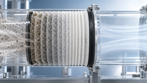
The central difference is that expanded polytetrafluoroethylene is commonly used as a microporous membrane layer rather than as a conventional depth-filtering web. Its structure encourages particles to remain close to the upstream surface. For pulse-cleaned dust collectors, intake filtration, automotive air systems, gas-turbine protection, and selected high-purity environments, that surface behavior can be more consequential than a headline efficiency figure.
The practical question is not simply whether an ePTFE membrane can stop fine dust. It usually can. The more useful questions are: how uniform are the pores, what sits beneath the membrane, how is the composite laminated, what contaminant is actually present, and how will the media behave after repeated loading, vibration, humidity exposure, or cleaning cycles?
The Microporous Structure Behind Filtration Performance
ePTFE is produced by expanding PTFE under controlled conditions, creating a network generally described as nodes connected by fine fibrils. This is not a simple drilled-film structure. The membrane contains a tortuous path made up of interconnected microscopic voids, and the geometry of that network determines much of its filtration behavior.
Pore size matters, but it should not be treated as the only design variable. A nominal pore-size value does not by itself describe pore distribution, membrane thickness, air permeability, mechanical integrity, or the effect of lamination. Two membranes with apparently similar pore specifications may behave differently once bonded to different substrates or exposed to different aerosols. In real filter construction, the membrane is one layer in a system.
For technical reviewers, the useful performance relationship is a balance rather than a single target:
A membrane with very restrictive pores may improve initial particle retention but raise pressure drop. Conversely, a more open structure can support lower resistance but may demand closer attention to the intended particle-size range and downstream requirements. That trade-off is why serious evaluation should compare media at a defined face velocity and under a stated test method, not by comparing isolated product descriptions.
Surface Filtration Changes the Dust-Loading Pattern
Traditional depth media captures particles throughout the thickness of a fibrous web. This can provide useful holding capacity, particularly where loading is gradual and replacement is preferred over cleaning. The downside is that fine dust can become lodged inside the fiber matrix. Once that happens, a cleaning pulse may remove only the surface portion of the deposit, while the embedded fraction remains and progressively raises residual pressure drop.
With ePTFE Filter Media, the membrane acts as a fine filtration skin on the upstream side of the supporting material. Particles are more likely to collect as a surface cake. In a pulse-jet cartridge or baghouse arrangement, this is a meaningful distinction: cleaning energy is directed toward a layer that is accessible instead of trying to dislodge dust from deep within the substrate.
Surface filtration is especially relevant for very fine, dry, free-flowing dusts that tend to blind conventional depth media. It can also be useful where downstream equipment is sensitive to particle breakthrough, such as certain precision manufacturing, energy, and air-intake systems. Still, “surface filtration” should not be read as “immune to fouling.” Sticky aerosols, oil mist, tar-like compounds, hygroscopic dust, and fibrous contaminants can foul nearly any media if the system is not designed around the actual contaminant.
There is also a common misunderstanding about dust capacity. A depth medium may appear to hold more dust within its structure before a visible cake forms. A membrane medium may instead develop a cake earlier because it is intentionally stopping particles at the surface. In a properly cleaned system, that early cake formation is not necessarily a disadvantage. The relevant measure is the stable operating pressure drop after repeated load-and-clean cycles, not only the mass loaded before the first cleaning event.
Dust Release Depends on More Than PTFE Surface Chemistry
PTFE is widely recognized for its low surface energy and chemical inertness. Those properties help explain why an ePTFE membrane can release many dry particulate deposits more readily than a rougher, uncoated fibrous surface. Less particle anchoring at the surface can mean a lower residual dust layer after cleaning, which is often the real driver of filter life in cyclic-duty equipment.
But dust release is a system result, not a material slogan. The same membrane can perform very differently when paired with a weak pulse, poor nozzle alignment, excessive filter length, unsuitable pleat geometry, or an unsupported substrate that flexes unpredictably. Dust characteristics are equally important. Particle shape, moisture uptake, electrical charge, temperature history, and the presence of oil or condensable vapors can all change adhesion behavior.
For example, a dry mineral dust and a plasticized process dust may have similar particle-size distributions yet clean very differently. The first may form a friable cake that detaches with a routine pulse. The second may smear, compact, or bridge across pores. In the latter case, changing the membrane alone may not solve the issue; upstream process control, pre-separation, temperature management, or a different filter architecture may be needed.
Technical teams should therefore ask for cleaning-cycle data where it is relevant, ideally generated under conditions that resemble the intended duty. Initial pressure drop is useful, but residual resistance after repeated cleaning often tells a more realistic story.
The Laminate Is Often the Deciding Factor
A membrane cannot be assessed in isolation from its backing and bonding process. The substrate provides tensile strength, processability, pleating behavior, and protection during filter manufacturing and operation. It may be cellulose-based, synthetic, spunbond, wet-laid, or a multi-layer engineered construction, depending on the final duty. The membrane must remain intact while the composite is converted, pleated, sealed, and exposed to airflow forces.
Bonding deserves particular scrutiny. Excess adhesive can partially obstruct the available porous structure or create stiff areas that crack under flexing. Too little bonding can leave the membrane vulnerable to lifting or delamination. Heat, pressure, adhesive chemistry, and web tension all need to be controlled. A construction suitable for a static ventilation panel may not be appropriate for a high-pulse industrial cartridge or an automotive filter subjected to vibration and moisture cycling.
This is where manufacturing breadth becomes relevant. Hangzhou Chaocai Materials Co., Ltd. develops functional advanced materials using fully synthetic wet-laid, PUR lamination, hot-melt adhesive lamination, solvent-based emulsion spray lamination, and ultrasonic lamination platforms. In filtration development, having multiple conversion routes is not just a production convenience. It allows the bonding approach to be matched to membrane sensitivity, substrate type, stiffness requirements, and the intended filtration environment rather than forcing every construction through one process.
For specialized applications in gas turbines, automotive systems, new energy equipment, semiconductors, or biopharmaceutical processing, the supporting layers and assembly method can be as application-specific as the membrane. The appropriate construction should be confirmed against the final filter design and relevant cleanliness, emission, or air-quality requirements.
How to Review an ePTFE Media Specification
A disciplined review starts by separating media properties from finished-filter performance. Finished filters are commonly evaluated under application-specific methods. For general ventilation, ISO 16890 is frequently used to classify air-filter performance by particulate matter size range. In North American HVAC practice, ASHRAE 52.2 is widely referenced. High-efficiency and HEPA/ULPA applications may involve ISO 29463 or EN 1822. These standards address filter performance within their scopes; they do not make one membrane construction universally suitable for every application.
For a media-level technical discussion, the following information is usually more useful than broad claims of “high efficiency” or “low resistance”:
- Basis weight, thickness, and air permeability of the complete laminate.
- Pressure-drop measurement conditions, including face velocity and specimen configuration.
- Particle challenge type and size range used for efficiency testing.
- Membrane orientation and whether the filtration layer faces the incoming air stream in the final element.
- Tensile, burst, flex, pleat, and adhesion requirements appropriate to conversion and service conditions.
- Chemical, temperature, humidity, and cleaning-pulse exposure expected in the actual process.
It is worth challenging any specification that gives efficiency without flow conditions, or pressure drop without stating the test setup. Those numbers may be technically correct but still impossible to compare. Likewise, chemical compatibility should be evaluated against the whole composite, including the backing, adhesive, sealant, and end-cap materials. PTFE itself may tolerate an exposure that the rest of the finished filter cannot.
Where Evaluation Can Go Wrong
One frequent mistake is selecting the lowest initial pressure-drop material without considering dust loading. Another is assuming that a membrane layer automatically solves every dust-release issue. In pulse-cleaned systems, pulse pressure, valve timing, cage design, filter geometry, and dust hopper behavior may be just as important as media selection.
A second mistake is overlooking conversion damage. Fine membrane media can be affected by aggressive pleating, poor handling, excessive thermal exposure, or incompatible sealing processes. Small defects may have limited visual evidence but can matter in applications with strict particle-control requirements. Incoming inspection and trial conversion should be part of qualification, especially when a media construction is being transferred to a new filter design.
Finally, do not rely solely on clean-air measurements. The value of ePTFE Filter Media is most visible when the test plan includes loading behavior, cleaning recovery where applicable, and post-conditioning integrity. That is where pore structure, surface filtration, and laminate design stop being abstract material concepts and become practical operating variables.
The best choice is usually the construction that delivers sufficient capture efficiency with stable resistance and repeatable manufacturability under the real duty cycle. For demanding systems, that judgment should be made from comparable test conditions and finished-filter trials—not from membrane type alone.
Recommendation
 Oct 10, 2026
How Can Air Filter Media Increase Dust Holding Capacity Without Higher Pressure Drop?
Which liquid filter media is suitable for hydraulic oil fine-particle filtration? Discover how advanced air filter media increases dust holding capacity with low pressure drop.- Oct 10, 2026
Which Liquid Filter Media Is Suitable for Fine Hydraulic Oil Filtration?
Can synthetic filter media replace glass fiber in high-humidity gas turbine intakes? Explore media choices for fine hydraulic oil filtration, balancing efficiency, moisture resistance, pressure drop, and service life. - Oct 10, 2026
Can Synthetic Filter Media Replace Glass Fiber in Humid Turbine Intakes?
Is ePTFE filter media suitable for pulse-cleaned construction equipment air filters? Explore synthetic vs. glass fiber performance in humid turbine intakes.