



How Can Filter Media Be Validated for High Humidity and Salt Fog?
Validation for high humidity and salt fog is not a single filter-efficiency test. A medium can retain particles well in a dry laboratory while its fibres swell, binder softens, pleat geometry distorts, conductive components corrode, or pressure drop rises sharply after repeated wet and saline exposure. The relevant question is whether the complete filter construction still provides its required airflow, filtration efficiency, mechanical integrity, and safe service life after exposure representative of the installation.
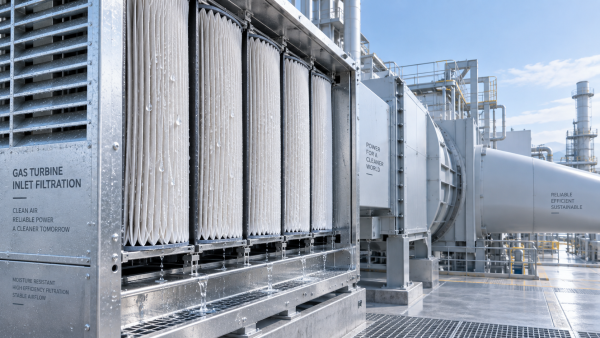
This distinction matters in coastal industrial sites, gas-turbine inlet systems, marine-adjacent facilities, vehicles operating on winter-treated roads, battery and power-electronics enclosures, and outdoor equipment near saltwater. In these environments, moisture is not merely a contaminant. It changes the physical state of the media and can carry dissolved salts into interfaces that are otherwise protected in dry operation.
Validate the finished filter, not only the media roll
Filter media testing remains essential, but salt-fog reliability is governed by the interaction of multiple materials. A filter element may include synthetic or cellulose-containing media, resin treatment, hot-melt separators, adhesive beads, polyurethane or plastisol potting, metal screens, expanded-metal supports, frames, gaskets, and protective coatings. Each interface can become the limiting point.
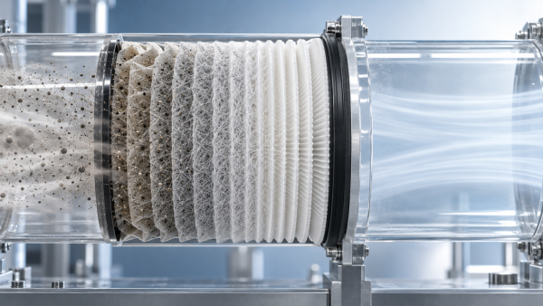
A material-level study is useful during formulation and supplier qualification. It can identify whether the fibre web loses tensile strength, whether a binder becomes tacky, or whether a hydrophobic treatment changes after exposure. It does not prove that a pleated element will remain stable. Pleat packs concentrate stress at fold lines, adhesive contact points, and media-to-frame joints; airflow creates loading that cannot be reproduced by examining a flat sheet alone.
For this reason, a robust program normally uses at least three specimen levels:
- Raw or converted media: for basis weight, thickness, tensile properties, water uptake, air permeability, and initial filtration characterization.
- Pleated packs or subassemblies: for pleat opening, separator adhesion, distortion, and adhesive compatibility.
- Finished filters: for corrosion, bypass resistance, pressure-drop stability, leakage, and post-exposure filtration performance.
The finished product should be exposed in its intended mounting orientation where practical. A horizontal panel, a vertical cartridge, and a V-bank element drain condensed water differently. Orientation can change where saline condensate accumulates and therefore which bond line fails first.
Define the environmental duty before selecting a test
“High humidity and salt fog” is not a complete test condition. A protected indoor system in a humid coastal city faces a different mechanism from an outdoor intake exposed to windborne marine aerosol, or an automotive enclosure subjected to splash, road salt, heat, vibration, and drying cycles.
The validation plan should define the exposure source and operating state. Important inputs include salt origin and chemistry; expected wetting frequency; temperature range; whether the filter operates while wet; airflow direction and velocity; periods of non-operation; drainage path; contaminant type; and the maximum acceptable consequence of failure. Sodium chloride is common in salt-spray testing, but industrial or road environments may contain additional salts and pollutants that alter corrosion and deposit behaviour.
Continuous salt spray is useful as an accelerated comparative screen, particularly for metallic frames, screens, fasteners, and coatings. It is not automatically a realistic predictor of field lifetime. Continuous wetness can overemphasize some mechanisms while missing the wet-dry concentration cycles that drive deposit formation, crevice corrosion, adhesive stress, and salt migration. Cyclic testing is often more informative when actual service includes intermittent wetting followed by drying or heating.
Relevant methods may include ISO 9227 for neutral salt spray and IEC 60068-2-52 for cyclic salt mist. Automotive applications may also draw environmental guidance from the ISO 16750 series, depending on the component and customer specification. These documents define test approaches; they do not, by themselves, establish that a filter is fit for every installation. Exposure severity, specimen conditioning, inspection rules, and functional acceptance criteria must still be tied to the actual application.
Humidity exposure must test moisture durability, not appearance alone
High relative humidity may cause gradual property changes even without visible condensation. Hygroscopic fibres can absorb moisture and change dimensions. Some binders may plasticize, lose stiffness, or exhibit hydrolysis under combinations of heat and moisture. Water-repellent treatments can be depleted or redistributed. In multilayer constructions, different expansion rates can create curl, delamination, or local stress at lamination points.
A useful humidity test therefore includes measurement before and after conditioning rather than a visual pass/fail check. Depending on the medium and duty, the assessment can include:
- change in air permeability or resistance to airflow;
- thickness, stiffness, and dimensional change;
- tensile strength and elongation in machine and cross directions;
- fibre shedding, surface cracking, and delamination;
- wet burst resistance or wet tensile strength where liquid contact is plausible;
- electrostatic charge retention, where filtration performance depends partly on electret charge;
- initial and post-conditioning particle efficiency across the relevant particle-size range.
Humidity conditioning should be followed by functional measurements after the specimen has reached a defined state. Testing only after complete dry recovery can hide an important operational weakness: the medium may perform acceptably once dried, yet exceed the permitted pressure drop or deform during a wet operating event. Where the filter is expected to run in humid air or intermittently wet conditions, performance should be measured both immediately after defined exposure and after recovery.
Salt fog introduces chemical and electrical risks
Salt deposits are hygroscopic. Even after apparent drying, they can attract moisture from humid air and maintain a conductive surface film. This affects more than corrosion. It can reduce insulation resistance in electrically active assemblies, alter conductive antistatic layers, promote leakage paths, and accelerate failure at dissimilar-metal contacts.
For conventional mechanical filters, the primary risks are usually corrosion and deposit-related airflow restriction. Corrosion products from galvanized or coated steel can stain the medium, obstruct local flow paths, weaken screens, and contaminate downstream equipment. Stainless steel is not automatically immune: alloy grade, weld condition, surface finish, chloride concentration, crevice geometry, and exposure temperature all matter. A nominally corrosion-resistant material should be evaluated in the actual assembly rather than assumed to be adequate based on material name alone.
For electrically enhanced or sensor-integrated filtration systems, salt-fog validation should also examine electrical continuity, insulation resistance, dielectric integrity where relevant, sensor output stability, and connector corrosion. These checks need to be performed at defined stages of the exposure cycle because a measurement taken only after thorough cleaning and drying may not reveal vulnerability during service.
Pressure drop is often the earliest functional warning
Visual corrosion can be minor while airflow performance has already become unacceptable. Salt deposits can bridge fibres, narrow pores, interfere with the open structure of a support layer, or form concentrated deposits at the upstream face. Humidity can further increase resistance by changing fibre geometry or holding deposited material in a wet agglomerate.
Pressure-drop measurements should use a controlled airflow rate appropriate to the filter’s rated duty. The comparison should distinguish between initial resistance, resistance during or immediately after wet exposure, resistance after drying, and resistance after a defined dust-loading stage if the application requires it. A filter that returns to its original clean pressure drop after drying may still be unsuitable if it experiences a temporary resistance peak that starves a turbine, cooling system, or ventilation enclosure of required air.
Post-exposure efficiency must be measured alongside resistance. A pressure-drop increase can occur because deposits block the medium, but a pressure-drop decrease may signal a more serious problem: separation of layers, cracking, rupture, or bypass around the media pack. Neither direction should be treated as automatically positive or negative without inspection and particle-performance data.
Assess filtration performance with the correct method and aerosol
The filtration standard should reflect the filter class and application. ISO 16890 is widely used for general ventilation air filters and characterizes efficiency against different particulate-matter size fractions. High-efficiency particulate air filters may require methods such as ISO 29463 or EN 1822, depending on the specification framework. Automotive, industrial, turbine, clean-process, and specialty filters can be governed by customer requirements or equipment-specific test procedures beyond these general standards.
Environmental durability testing should not replace the applicable filtration performance test. It should be added as a conditioning stage, followed by the relevant efficiency and leakage measurements. The test aerosol must also be chosen carefully. A method developed to classify a general ventilation filter may not answer whether a medium will maintain protection against the particle distribution critical to a compressor inlet, battery enclosure, or sensitive production process.
When a medium relies on electret capture, test planning deserves particular attention. Moisture, salt contamination, surfactants, solvents, and thermal exposure can affect charge-based mechanisms differently. A satisfactory result under a single dry aerosol condition does not establish post-exposure stability. The acceptance requirement should state whether efficiency must remain above a minimum value after conditioning, whether a percentage change is allowed, and whether the limit applies at the most penetrating particle-size range or at a system-specific size range.
Use cycles that reproduce combined stress, not isolated laboratory events
Separate humidity and salt-spray tests are useful for diagnosis, but combined cycling is often closer to the failure mechanism. Salt is deposited during mist exposure; water remains in interfaces; heat and drying concentrate the salt; cooling drives condensation; airflow applies mechanical loading. The sequence can be more damaging than any single step.
A practical validation matrix may include a baseline characterization, humidity conditioning, salt-fog or cyclic salt-mist exposure, controlled drying or thermal cycling, and repeat exposure. If the filter is used under vibration or pressure pulses, those loads should be incorporated or assessed separately because a softened adhesive joint may fail only when mechanical stress is added.
Test duration should not be selected as a generic number of hours merely because it is familiar in another industry. The duration and number of cycles need a rationale linked to expected service exposure, severity classification, customer requirements, and the consequence of failure. Accelerated testing is comparative evidence, not a direct conversion formula from chamber hours to field years.
Set acceptance criteria before exposing samples
A test report that says “no obvious damage” is rarely sufficient for procurement or engineering approval. Acceptance criteria should be agreed before testing and should combine function, integrity, and corrosion assessment.
Typical criteria can include a maximum allowable change in pressure drop at the rated airflow; a minimum retained efficiency; no visible media rupture, delamination, or pleat collapse; no loss of seal or potting adhesion; no unacceptable corrosion on components that affect structural or airflow performance; no leakage beyond the specified limit; and no unacceptable change in electrical properties for active systems. Dimensional limits may be needed where swelling prevents installation or creates a bypass path.
Inspection should include disassembly when feasible. External surfaces can look intact while corrosion is progressing beneath a gasket, inside a folded edge, or under a protective adhesive bead. Cross-sections and close examination of media-to-frame interfaces are especially valuable after cyclic exposure.
Replicate specimens are important because filter media and converted elements have natural variation. A single passing unit can conceal sensitivity to pleat formation, adhesive application, coating thickness, or local material variability. The test record should identify material batch, media orientation, pleat geometry, adhesive type, frame material, mounting condition, airflow rate, exposure profile, recovery conditions, measurement equipment, and any deviations from the planned procedure.
Common validation errors that create false confidence
The most frequent error is treating corrosion resistance of the frame as proof of filter durability. This overlooks wet-strength loss, media swelling, bond degradation, and changed filtration efficiency. The opposite error is testing a flat media coupon only and assuming the result applies to a finished pleated element.
Another weak practice is measuring performance only before exposure and after a long recovery period. This can miss transient failures during wet operation. It is also risky to run a salt-fog test without defined cleaning rules. Rinsing deposits before performance measurement may be appropriate for some objectives, but it answers a different question from testing the element with residual salt present. The protocol must state whether the goal is corrosion durability, operational performance under deposited salt, or both.
Finally, salt fog should not be used as a substitute for realistic contaminant loading. Marine aerosol, ordinary dust, oil mist, soot, and process particles can interact differently with moisture. Where the installed filter sees mixed contaminants, a separate dust-loading or combined contamination evaluation may be necessary.
What a defensible validation decision looks like
Filter media can be considered validated for high humidity and salt fog only when the selected construction retains the required function after a justified environmental profile. That conclusion should rest on evidence from the complete assembly: stable pressure drop, retained particle performance, intact pleats and bonds, controlled corrosion, no unacceptable bypass, and—where relevant—stable electrical behaviour.
The strongest specification does not simply request a salt-spray certificate. It defines the operating environment, identifies the likely failure mechanisms, requires appropriate conditioning cycles, specifies post-exposure functional tests, and sets measurable acceptance limits. This approach gives manufacturers and buyers a clearer basis for comparing materials that may appear similar in an initial efficiency test but behave very differently once moisture and salt become part of normal operation.
Recommendation
 Oct 10, 2026
How Can Air Filter Media Increase Dust Holding Capacity Without Higher Pressure Drop?
Which liquid filter media is suitable for hydraulic oil fine-particle filtration? Discover how advanced air filter media increases dust holding capacity with low pressure drop.- Oct 10, 2026
Which Liquid Filter Media Is Suitable for Fine Hydraulic Oil Filtration?
Can synthetic filter media replace glass fiber in high-humidity gas turbine intakes? Explore media choices for fine hydraulic oil filtration, balancing efficiency, moisture resistance, pressure drop, and service life. - Oct 10, 2026
Can Synthetic Filter Media Replace Glass Fiber in Humid Turbine Intakes?
Is ePTFE filter media suitable for pulse-cleaned construction equipment air filters? Explore synthetic vs. glass fiber performance in humid turbine intakes.