



Industrial Air Filter Media: How MERV and ISO 16890 Ratings Affect System Design
A filtration rating is a design input, not a complete filter specification. MERV and ISO 16890 both describe particle-removal performance, yet they test, classify, and communicate that performance differently. Treating a MERV value as a direct equivalent of an ISO 16890 class can lead to an air-handling system with the wrong resistance profile, an unsuitable final filter stage, or maintenance intervals that do not match the actual dust load.
For industrial ventilation, clean production areas, gas turbine intake systems, automotive manufacturing, semiconductor support spaces, and process air systems, the selected Air Filter Media affects the whole operating point of the system. Fan static pressure, available motor margin, airflow stability, coil cleanliness, downstream equipment protection, and replacement planning all follow from the interaction between media efficiency and resistance. The rating identifies an important part of that interaction, but the media construction and operating conditions determine whether the specified filter will perform as intended after installation.
MERV and ISO 16890 answer related but different questions
MERV, defined by ASHRAE Standard 52.2, classifies a filter according to its ability to capture particles over specified size ranges. Its reported efficiency values are commonly expressed through ranges that distinguish larger coarse particles from smaller particles in the approximate 0.3 to 1 micrometer range. A higher MERV rating generally indicates stronger removal of finer particles under the test method.
ISO 16890 classifies filters through fractional efficiency measured across a particle-size distribution, then groups performance around the PM1, PM2.5, and PM10 fractions. The resulting classes, such as ISO ePM1, ISO ePM2.5, ISO ePM10, and ISO Coarse, connect the filter result more directly to particulate fractions used in ambient-air discussions. The class should be read together with its stated efficiency value. “ISO ePM1 60%,” for example, communicates both the particle fraction and the measured efficiency level; “ISO ePM1” alone does not define an equivalent performance point.
The two systems should therefore be used as parallel descriptions rather than as interchangeable labels. Conversion charts can support preliminary comparison, but they compress a full efficiency curve into a simplified cross-reference. They cannot establish equal initial pressure drop, equal dust-holding behavior, equal resistance rise, or equal performance after electrostatic charge changes.
The fine-particle target sets the filtration architecture
System design should begin with the contamination that must be controlled at the protected component or process, not with a preferred rating number. A coarse prefilter is often selected to remove fibers, insects, visible dust, and larger mineral particles before they load a higher-efficiency final stage. Its job is frequently to preserve the service life and airflow stability of the downstream filter rather than to deliver final air cleanliness on its own.
Where fine particulate reaches sensitive heat exchangers, precision process zones, turbine compressor sections, or controlled manufacturing spaces, the final stage needs meaningful efficiency in the relevant fine-particle range. Raising the final-stage rating without reconsidering the prefilter can shorten service life because the higher-efficiency element receives a large mass of coarse dust. Conversely, using an aggressive prefilter with excessive initial resistance can consume fan-pressure allowance before the final filter begins to load.
A two-stage system must be evaluated as a system. The pressure drop of each filter at the design airflow is additive, while dust loading shifts both elements over time. A specification that lists only the final filter rating leaves unresolved questions about prefilter efficiency, filter face area, permitted final resistance, and the fan curve. Those omissions are common sources of airflow shortfall after commissioning.
Pressure drop is a media and geometry issue
Filters with similar rated efficiency can have materially different initial resistance. Fiber diameter, basis weight, web density, pore structure, electrostatic treatment, pleat depth, pleat spacing, separator design, and effective media area all affect airflow resistance. A denser layer may improve mechanical capture, while a larger pleated area can offset some of the resistance introduced by that layer. Neither benefit should be inferred from the rating alone.
Media using electrostatic attraction deserves particular attention. An electret structure can show efficient fine-particle capture at a favorable initial pressure drop. Under test procedures that condition the media, or under field exposure to certain aerosols and humidity conditions, its performance profile can change. This is not an argument against charged media; it is a reason to require performance information aligned with the installation environment and the governing standard. Where stable mechanical efficiency is essential, the specified data should make clear how the filter performs beyond an unconditioned initial state.
Filter geometry also changes the meaning of a pressure-drop value. A compact panel, a deep-pleated filter, and a pocket filter may use related media grades but present different air-to-media ratios. A lower face velocity reduces local media velocity when adequate area is available, generally reducing resistance and improving dust capacity. Installing a high-efficiency filter in a shallow housing with insufficient area often creates high velocity through the pack, rapid loading, and uneven airflow distribution.
Use the whole pressure budget
The available external static pressure must cover more than a clean filter. Include the expected loaded resistance of every filter stage, coils, dampers, duct fittings, silencers, hoods, and any terminal devices. Fan selection should be checked at the required airflow across the anticipated resistance range, with motor capacity and control range verified at the loaded condition.
A filter bank that meets airflow at startup but cannot maintain it as resistance rises is not a successful design. The practical replacement point should be set before the system falls below required flow, exceeds an acceptable energy level, or compromises the process pressure relationship. Using only a calendar interval ignores seasonal particulate changes, construction dust, process emissions, and unexpected upstream contamination.
Initial efficiency does not predict service life
Dust-holding capacity is often interpreted too simply. A filter can retain substantial test dust yet still be unsuitable for a real installation if the dust is fine, sticky, fibrous, oily, damp, or highly variable. Surface-loading media may build a cake near the upstream face, which can be useful for some dust types but may create a rapid pressure rise. Depth-loading media can distribute particulate through the structure, although its field behavior still depends on fiber architecture and the shape of the particles.
Industrial air frequently contains mixed contaminants. Welding fume, oil mist, machining aerosols, moisture, salt, cellulose fibers, carbon dust, and mineral particles do not load media in the same way. Gas-phase contaminants require separate adsorbent or chemical filtration considerations; a MERV or ISO 16890 particulate rating does not demonstrate vapor removal. Similarly, water droplets or persistent high humidity can alter media resistance, encourage microbial concerns in unsuitable assemblies, or damage components that were intended for dry service.
The replacement strategy should rely on differential-pressure trend data, airflow or fan-speed behavior, and visual inspection of upstream conditions. A sudden pressure increase may indicate unusual dust exposure or a collapsed filter pack. A weak pressure change accompanied by declining airflow may point instead to a bypass path, damper issue, fan-control problem, or an inaccurate sensing arrangement. These symptoms should not be treated as evidence of filter performance without inspection.
Installation leakage can erase a rating advantage
Rated efficiency applies to air passing through the tested filter media and its intended construction. Air bypassing the frame, gasket, holding track, door seal, or damaged bank does not receive that filtration. A small gap is especially consequential where fine-particle control is the purpose of the final stage, because the leak path has almost no resistance compared with the media.
Housing design should provide a stable clamping surface and retain the filter without warping the frame. Gaskets must be continuous and compressed consistently. Field inspection should look for missing clips, distorted tracks, bowed access doors, torn media, improper filter orientation, and filters that do not match the nominal housing dimensions closely enough to seal. Differential-pressure taps should be placed so they measure the filter bank rather than a local turbulence zone or a mixture of unrelated system losses.
Transport and storage also matter. Pleated media can be damaged by compression, vibration, moisture exposure, or careless stacking before the filter reaches the site. A filter delivered with intact packaging but deformed pleats may show higher resistance and reduced usable area. Receiving inspection is most useful when it confirms dimensions, airflow direction, gasket condition, frame rigidity, and visible media integrity before installation work closes the access path.
Specification language that reduces ambiguity
A robust submittal requirement identifies the applicable rating system and asks for the information needed to model operation. “High-efficiency filter” is too vague. “MERV 13” alone is more precise, but it still does not establish a pressure-drop limit, final resistance, test airflow, media type, dimensions, or construction. The same issue arises with an ISO designation that does not include its ePM percentage.
- State the required MERV rating under the applicable ASHRAE test method, or state the ISO 16890 classification with its full ePM efficiency value.
- Define the rated airflow and maximum initial pressure drop for the exact filter size and configuration, rather than accepting data from a different nominal size.
- Set the allowable final resistance in relation to fan capability and minimum process airflow.
- Describe frame material, gasket arrangement, moisture exposure limits, temperature conditions, and any flame, corrosion, or cleanliness constraints relevant to the location.
- For staged banks, identify the sequence and the intended function of each stage so substitutions do not shift all loading onto one element.
When existing facilities use MERV terminology and a new filter submittal is expressed only under ISO 16890, the comparison should examine the full efficiency information and the pressure-drop curve. A nominally comparable class is not sufficient evidence that the replacement will preserve airflow, equipment protection, or maintenance behavior. The same discipline applies in the opposite direction when an ISO-based specification receives a MERV-only offer.
Matching the rating to the operating environment
For general industrial make-up air, a coarse first stage combined with a final filter selected for the relevant fine-particle exposure often offers a workable balance. The final choice changes where outdoor pollution is elevated, nearby handling creates fine dust, or downstream coils and controls are difficult to clean. Systems serving controlled rooms require the filter bank to be coordinated with room pressurization, air-change requirements, and any terminal filtration already present. Adding a high-rated central filter without reviewing terminal stages can create redundant resistance with limited process benefit.
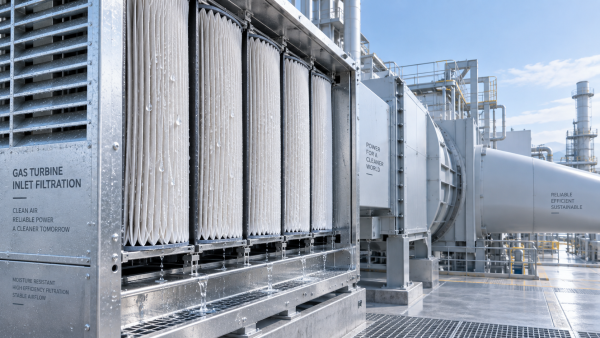
Gas turbine intake filtration introduces a separate loading profile. Fine particulate, water, salt, and pulse-cleaning arrangements can make water resistance, mechanical stability, and filter geometry as important as the nominal particle rating. A filter selected only by a familiar HVAC rating may not suit the intake housing, weather hood arrangement, or pressure constraints of that equipment.
The useful comparison is therefore not “which rating is higher?” It is whether the stated particle efficiency, resistance curve, media construction, seal integrity, and expected loading behavior support the required airflow and protection level throughout the planned service interval. MERV and ISO 16890 provide the language for that evaluation; system design gives the rating its operational meaning.
Recommendation
 Oct 10, 2026
How Can Air Filter Media Increase Dust Holding Capacity Without Higher Pressure Drop?
Which liquid filter media is suitable for hydraulic oil fine-particle filtration? Discover how advanced air filter media increases dust holding capacity with low pressure drop.- Oct 10, 2026
Which Liquid Filter Media Is Suitable for Fine Hydraulic Oil Filtration?
Can synthetic filter media replace glass fiber in high-humidity gas turbine intakes? Explore media choices for fine hydraulic oil filtration, balancing efficiency, moisture resistance, pressure drop, and service life. - Oct 10, 2026
Can Synthetic Filter Media Replace Glass Fiber in Humid Turbine Intakes?
Is ePTFE filter media suitable for pulse-cleaned construction equipment air filters? Explore synthetic vs. glass fiber performance in humid turbine intakes.