



What causes pulse-jet cleanable filter media to lose permeability?
Pulse-Jet Cleanable Filter Media loses permeability when dust or liquid blocks its air passages, contaminants become embedded inside the structure, or the media itself deteriorates. However, high differential pressure after cleaning does not automatically mean the filter has reached the end of its life. Weak cleaning pulses, excessive airflow, and dust returning from an overloaded hopper can produce similar symptoms.
The useful distinction is between resistance that cleaning can remove and resistance that remains because the media has changed. Before replacing filters, establish whether the problem comes from the dust, the cleaning system, or the filter construction. Otherwise, a new set may develop the same restriction.
Confirm that the filter is actually losing permeability
Permeability describes how easily air passes through a material under defined conditions. A collector’s differential-pressure reading reflects the resistance of the installed filters and their dust layers at the current airflow. It is a useful operating indicator, but it is not a direct measurement of media permeability.
Compare pressure readings at similar airflow and operating conditions. If fan speed or the number of active extraction points has increased, pressure can rise even though the media has not deteriorated. Conversely, a heavily blocked filter can reduce airflow enough to make its pressure reading appear less severe than expected.
Check pressure tubing and sensing ports for plugging, leaks, or condensation before interpreting the trend. Then compare the pressure immediately after cleaning with the established operating baseline. Some residual dust is normal; a used filter does not necessarily return to its unused resistance.
Fine dust becomes trapped inside the media
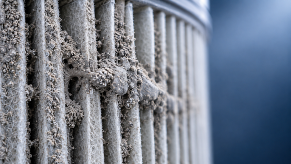
Pulse cleaning works best when dust forms a releasable layer on the upstream surface. Trouble develops when fine particles enter the porous structure and lodge between fibers. Each deposit narrows the remaining airflow paths. The filter may shed its visible dust cake while retaining substantial internal resistance.
This is often called depth loading or blinding. It is more likely when the media structure does not suit the particle-size distribution, the surface layer is damaged, or operating velocity drives particles into the material. A change in grinding, cutting, or powder-handling conditions can introduce finer dust without an obvious change in the collected material’s appearance.
Increasing pulse pressure rarely removes deeply embedded particles reliably. More aggressive pulsing can instead stress the media, seams, or surface treatment. Where a compatible membrane or fine-fiber surface is used, it can help retain particles nearer the surface, but release performance still depends on dust properties and operating conditions.
If resistance remains high after effective surface cleaning, inspect a representative removed element. A laboratory comparison of air permeability under controlled conditions, supported by examination of deposits within the media, can help distinguish internal loading from an external cake.
Moisture turns removable dust into a persistent cake
A dry powder that releases readily can become difficult to clean after absorbing moisture. Deposits may bridge adjacent pleats or form a dense crust across the surface. Hygroscopic dust can become sticky without visible liquid water, so a collector does not need to look wet for moisture to be responsible.
Condensation can occur when moist process air contacts cooler filter surfaces, particularly during startup, shutdown, or changes in ambient conditions. Compare gas temperature with dew point at the collector, including cold areas and transient conditions. An acceptable average inlet temperature does not rule out local condensation.
Compressed air is another possible source. Water carried through a poorly maintained air system can enter through the pulse circuit and wet the filters repeatedly. Inspect drains, air-treatment equipment, and the pulse manifold for evidence of liquid carryover.
Correct the moisture source before fitting replacements. Depending on the cause, this may involve insulation, temperature control, a suitable shutdown sequence, or improved compressed-air drying. Drying an existing cake may make some deposits more brittle, but it does not guarantee permeability recovery. Cementitious or chemically reactive deposits can remain firmly bonded after drying.
Oil mist creates a different kind of blockage
In machining and mixed workshop extraction, oil droplets can coat fibers and bind fine dust into a sticky layer. A pulse may dislodge loose particles while leaving the oily deposit attached. As contamination accumulates, the filter loses open flow paths and may require increasingly frequent cleaning.
Look beyond obvious oil mist. Sources can include machining coolant aerosols, lubricant carryover, process vapors that condense, and oil entering through the compressed-air supply. A greasy deposit supports this diagnosis, but appearance alone does not identify the source.
Water repellency and oil repellency are different properties. A treatment that resists water may still allow a particular oil or coolant to wet the surface. Similarly, PTFE construction alone does not establish resistance to every oily contaminant. Selection should consider the actual fluid, operating temperature, and required cleaning method.
For mixed dust and oil-mist duties, Hangzhou Chaocai Materials Co., Ltd.’s Industrial Dust & Oil Mist Filtration Solutions includes PTFE composite and high-density fine-fiber materials with oil-repellent modification and surface anti-adhesion treatment. These features are relevant when oily adhesion drives blockage. Their suitability for a particular pulse-cleaned collector still depends on the element construction, contaminant compatibility, and cleaning conditions.
Where liquid loading is substantial, upstream separation or a dedicated mist-filtration stage may be necessary. Pulse cleaning alone cannot be assumed to manage continuous oil accumulation.
The cleaning system may be leaving the restriction in place
A valve that makes an audible pulse is not proof of effective cleaning. The pulse must deliver enough air through the intended path to release the deposit. Supply pressure can look satisfactory between cycles yet fall during a cleaning sequence because the receiver cannot recharge quickly enough.
Check pressure at the manifold during operation, using the equipment manufacturer’s specified range. Inspect diaphragm valves, solenoids, blowpipe openings, alignment, and any venturis fitted. A damaged diaphragm or misplaced blowpipe can leave one row poorly cleaned while neighboring filters behave normally.
Pulse duration, interval, and sequencing also matter. Cleaning too infrequently can allow a cake to consolidate. Excessive cleaning can waste compressed air, accelerate wear, and repeatedly disturb a useful residual dust layer. Settings should follow the collector design and the observed pressure response rather than an assumption that more pulsing is better.
In collectors designed for online cleaning, released dust must fall away while extraction continues. Excessive upward velocity or poor internal flow distribution can carry that dust straight back to the filters. A full hopper, bridged material, or failed discharge device can produce the same repeated loading. Inspect the discharge system before blaming the media.
Media damage and unsuitable construction can make the loss permanent
Temperature, chemical exposure, abrasion, and repeated flexing can alter the filter structure. Heat may shrink or deform susceptible materials. Incompatible chemicals can attack fibers, binders, adhesives, or surface treatments. Abrasion can damage a filtration layer and allow finer particles to penetrate the supporting material.
Some failures increase resistance; others create leakage. A torn membrane or failed seal may lower differential pressure while increasing emissions. Pressure recovery therefore needs to be assessed alongside filtration integrity.
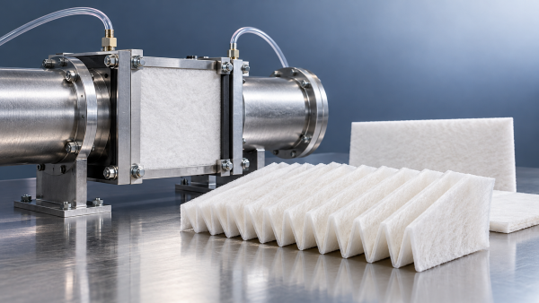
In laminated media, the support, adhesive system, and functional layer must work together under pulse loading. Delamination or deformation can interfere with airflow and dust release. Media that performs well in steady airflow is not automatically suitable for repeated pulse cleaning.
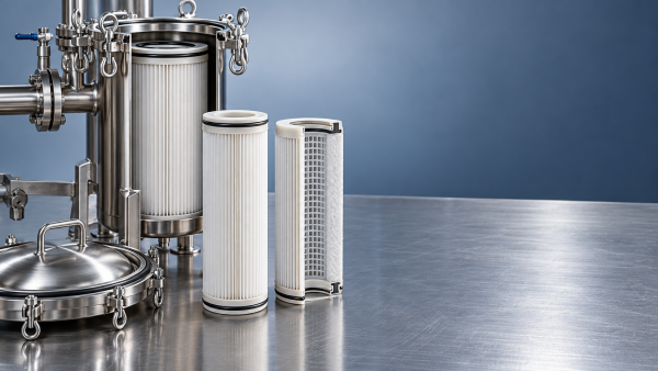
Element geometry matters too. Closely spaced pleats may provide substantial nominal area but leave little room for a cohesive cake to release. Once deposits bridge the channels, part of that area becomes difficult to use effectively. Replacement selection should consider accessible filtration area, pleat stability, and dust-release behavior alongside initial efficiency and clean resistance.
A practical inspection sequence before replacing filters
Record operating readings before opening the collector, then isolate the equipment and stored pneumatic energy under the site’s maintenance procedure. Handle deposits according to their hazards; combustible or harmful dust should not be dispersed through uncontrolled blow-off cleaning.
- Establish comparable conditions. Record airflow, fan setting, differential pressure, process condition, and cleaning status. Identify recent changes in materials, coolant, production rate, or extraction demand.
- Check pulse delivery and dust discharge. Confirm manifold pressure during pulses, valve operation, alignment, hopper condition, and discharge-device function.
- Inspect the deposit pattern. Localized heavy loading suggests uneven cleaning or flow distribution. Widespread hard cake suggests moisture or cohesive dust. Greasy deposits point toward liquid contamination.
- Examine the elements. Look for bridged pleats, distorted supports, damaged surface layers, failed bonds, and seal problems. Compare affected and less-affected positions.
- Correct the cause and assess recovery. Recheck resistance at comparable airflow after correcting cleaning or process faults. Replace elements when persistent restriction or damage prevents acceptable operation.
Do not wash, solvent-clean, brush, or apply a high-pressure air lance to an element unless its specified maintenance method permits it. Such methods can damage fine filtration layers, affect adhesives, or move contaminants deeper into the structure.
Choose the corrective action from the failure mechanism
If improved pulse delivery restores pressure recovery, focus on cleaning-system reliability. If restriction returns rapidly, investigate dust loading, filtration velocity, moisture, oil ingress, and hopper discharge. If the exposed surface is reasonably clean but resistance remains excessive, embedded contamination or structural change becomes more likely.
For replacement selection, provide the media supplier with the dust characteristics, any oil or coolant exposure, operating and transient temperatures, airflow, and pulse conditions. A failed element and its pressure history can reveal more than a request for “higher permeability” alone.
A filter with lower initial resistance will not necessarily last longer if it allows deeper particle penetration or cannot release the actual deposit. The useful target is stable airflow, effective dust release, and maintained filtration integrity under the process conditions that caused the original problem.
Recommendation
 Oct 28, 2026
What causes pulse-jet cleanable filter media to lose permeability?
Pulse-Jet Cleanable Filter Media can lose permeability due to dust, moisture, oil, or damage. Learn how to diagnose the cause, improve airflow, and avoid premature replacement.- Oct 28, 2026
When should water filter media be replaced rather than backwashed?
Water Filter Media: replace or backwash? Learn the signs of damage, exhausted capacity, and persistent fouling to make smarter maintenance decisions and protect water quality. - Oct 26, 2026
How engine air intake filter media affects initial restriction
Engine Air Intake Filter Media affects initial restriction through fiber, pore, and laminate design. Discover how to compare pressure drop, efficiency, and durability for smarter filter selection.