



How Does ePTFE Media Affect Initial Pressure Drop?
When a filtration system is expected to capture fine particles without restricting airflow, initial pressure drop quickly becomes a practical design concern. A gas turbine intake filter may need stable air delivery at high flow rates; an automotive air filter may need to protect downstream components without increasing engine intake resistance; a semiconductor or biopharmaceutical process may require controlled particle capture while maintaining predictable system conditions. In each case, a media choice that appears efficient on paper can create problems if its resistance is not understood in the finished filter configuration.
How does ePTFE media affect initial pressure drop? ePTFE can help achieve a relatively low initial pressure drop at a required filtration efficiency because its membrane structure can provide highly controlled, interconnected pores in a thin filtration layer. However, ePTFE does not automatically produce the lowest resistance. Initial pressure drop depends on the membrane’s pore structure, thickness, basis weight, lamination method, support layer, airflow direction, face velocity, and the geometry of the completed filter. A restrictive membrane or poorly designed laminate can raise resistance even when the base material is highly porous.
Why initial pressure drop matters before the filter starts loading
Initial pressure drop is the airflow resistance measured when a clean filter is first placed into operation. It is often treated as a simple starting value, but it influences several later decisions: fan or blower sizing, energy consumption, airflow stability, maintenance intervals, and the available margin before a filter reaches its service limit.
A low initial pressure drop is especially valuable where airflow demand changes rapidly or where the system has limited pressure capability. In a turbine intake application, excessive resistance can affect inlet conditions. In an automotive air system, it may limit available air delivery as flow demand rises. In high-cleanliness manufacturing environments, a pressure drop increase may require changes to air handling settings that can affect process control. The clean-media resistance therefore needs to be evaluated as part of system performance, not only as a standalone laboratory property.
At the same time, the lowest possible pressure drop is not always the correct target. Opening the pore structure too far can reduce fine-particle capture or allow particles to penetrate deeper into the media. The useful question is usually not “Which media has the lowest resistance?” but “Which media reaches the required efficiency with the least practical resistance in this operating condition?”
What ePTFE changes in the airflow path
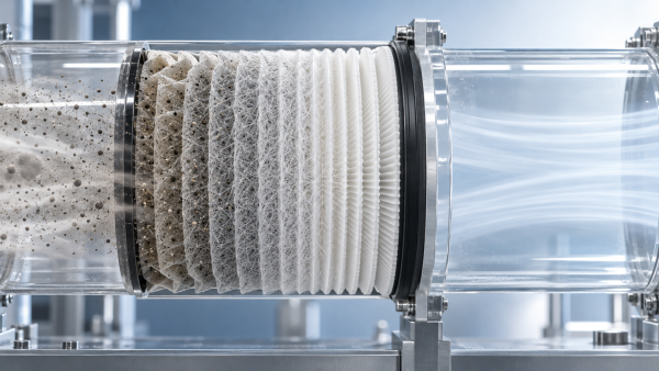
Expanded polytetrafluoroethylene is formed into a microporous structure with nodes and fibrils. The resulting membrane can contain a large open volume while still presenting small, controlled pathways to airborne particles. When used as a filtration layer, it commonly sits on a supporting substrate because the membrane itself may be too thin or delicate to provide the strength, pleat stability, or handling characteristics required by the final product.
Air does not pass through a membrane as though it were moving through large, straight openings. It follows a network of tortuous paths. Resistance is affected by the size and distribution of those paths, how many are available per unit area, and how long the air must travel through the layer. A thin ePTFE membrane with sufficient open structure can offer less resistance than a thicker depth-filtering construction designed to reach the same fine-particle efficiency.
This is one reason ePTFE is often considered for demanding filtration duties. Fine-particle capture can occur near the membrane surface rather than relying entirely on particles traveling into a thick fibrous web. The membrane may therefore support high initial efficiency without requiring a heavily densified substrate. Yet the membrane remains only one part of the airflow route. Once it is bonded to a nonwoven, coated, pleated, sealed, or otherwise converted, the pressure drop belongs to the composite filter rather than to ePTFE alone.
A thin membrane can lower resistance at equal efficiency, but only under the right comparison
ePTFE is sometimes described as “low pressure drop media,” which is incomplete. Adding any membrane layer to an open support generally introduces some additional resistance. The important comparison is between complete media systems delivering the same filtration result.
For example, a conventional depth media may need to be made denser, thicker, or more layered to capture a specified fraction of fine particles. That construction can produce substantial clean resistance because the airflow must move through a longer and more restrictive fiber network. A properly selected ePTFE laminate may meet the same capture requirement through a thinner, more uniform surface-filtration layer, allowing the support media to remain comparatively open. In that comparison, the ePTFE-based composite can have a favorable initial pressure drop.
The opposite can also occur. If the membrane pore structure is too fine for the actual particle target, if the membrane is thicker than necessary, or if the support has low permeability, the finished media can show a higher-than-expected clean resistance. This is why a membrane’s nominal pore description should not be used as the only selection criterion.
Factors that determine the initial pressure drop of ePTFE media
Membrane pore architecture
Pore size matters, but average pore size alone does not explain airflow resistance. A membrane with a narrow and consistent pore distribution can provide more predictable filtration behavior than one with a broad distribution containing a mix of very open and highly restrictive regions. The number of available flow paths, their connectivity, and the degree of tortuosity all influence clean-air permeability.
Very fine structures can improve capture of small particles, but smaller pathways generally increase resistance. A design intended for ultrafine particle control may therefore have a different pressure-drop profile from one used for coarse dust or liquid droplet separation. The filtration target must define how much restriction is acceptable.
Membrane thickness and mass
All else being equal, air encounters greater resistance when it must travel through a longer microporous path. A thinner ePTFE layer can help limit initial pressure drop, provided it still maintains the necessary integrity and capture performance. Thickness cannot be reduced indefinitely. The membrane must withstand converting, pleating, vibration, pulse cleaning where applicable, and service conditions without damage or unacceptable pore changes.
Thickness should also be considered after lamination. Adhesive penetration, compression during bonding, and the addition of reinforcing layers may alter the effective air path. A low-resistance membrane can lose part of its advantage when the total laminate is not designed around airflow.
Support substrate permeability
The support is frequently the hidden source of resistance. Even when an ePTFE membrane is highly permeable, a dense nonwoven backing, restrictive scrim, coating, or secondary layer can dominate the pressure-drop result. This becomes more likely when the substrate is selected primarily for strength, stiffness, printability, or processing convenience without sufficient attention to air permeability.
A useful evaluation separates the components. Test the support, the membrane, and the laminated composite under the same airflow conditions. The results do not always add in a perfectly linear way, but this approach can reveal whether the support structure is consuming too much of the available pressure-drop budget.
Lamination method and adhesive distribution
Lamination is necessary for many ePTFE constructions, but it must preserve open flow area. Adhesive that migrates into the membrane pores can block pathways and increase resistance. Excessive bonding pressure or heat can also compress the support and reduce its permeability. These effects may be uneven across the roll, creating variation from one filter element to another.
Different lamination approaches can be selected according to material compatibility and required durability. PUR lamination, hot-melt adhesive lamination, solvent-based emulsion spray lamination, and ultrasonic bonding each create different bonding patterns and thermal or mechanical effects. The correct process is not simply the strongest bond. It is the process that provides adequate adhesion and processing stability while minimizing obstruction of the active filtration area.
Face velocity in the actual filter
Pressure drop rises as more air is pushed through a given area of media. A material that performs well at a modest laboratory face velocity may become restrictive when installed in a compact element with limited effective area. This is one reason a media comparison should use the intended operating range rather than a single convenient test point.
Filter geometry matters just as much as media permeability. Pleat depth, pleat count, pleat spacing, usable media area, pack compression, and airflow distribution all influence the local velocity through the membrane. Areas near seals, frames, or uneven inlet zones may experience higher localized loading and resistance than the average system calculation suggests.
Surface filtration changes how pressure drop develops after installation
Although initial pressure drop is measured on clean media, the way ePTFE captures particles affects what happens next. ePTFE membranes often promote surface loading because particles are retained close to the upstream side of the membrane instead of deeply embedding throughout a fibrous structure. This can improve capture consistency and make dust-cake behavior more predictable in some dry filtration applications.
Surface loading does not guarantee slow pressure-drop growth. A fine, cohesive dust may quickly form a dense cake on the membrane surface. Moisture, oil aerosols, sticky contaminants, and electrostatic effects can change the structure of that cake. The initial pressure drop may be low, yet the operating pressure drop can rise rapidly when the challenge aerosol is poorly suited to the membrane configuration.
Conversely, some depth media begin with a low clean resistance but gradually lose permeability as particles penetrate and block internal pathways. Comparing only clean-media pressure drop can therefore lead to the wrong decision. The expected contaminant type, concentration, particle-size distribution, humidity, and service cycle should be considered alongside the initial value.
How to evaluate ePTFE media without drawing the wrong conclusion
When two media options are being reviewed, start by defining the operating point rather than asking for a general “low pressure drop” construction. The test condition should reflect the fluid, flow direction, temperature, humidity where relevant, and anticipated face velocity. A comparison is meaningful only when both materials are tested at equivalent efficiency targets and comparable finished-media configurations.
- Set the required filtration objective. Identify the particle-size range, efficiency expectation, and whether the system is mainly protecting equipment, controlling process contamination, or extending downstream component life.
- Establish the allowable clean resistance. Use the system’s available pressure margin, not merely a preferred media value. Include the effect of housings, grilles, ductwork, seals, and other components that add resistance.
- Check the ePTFE-support combination. Ask whether the support remains sufficiently open after lamination and whether the bonding method avoids excessive pore blockage or compression.
- Evaluate the intended geometry. Determine effective media area and local face velocity after pleating or assembly. Flat-sheet results are useful, but they cannot fully predict a compact filter element.
- Review loading behavior. Consider whether particles are dry, oily, hygroscopic, abrasive, fibrous, or prone to forming a compact cake. The initial value should be read together with the expected pressure-drop curve over service life.
A supplier’s media data can be a useful starting point, but it should be matched to the actual conversion process. Differences in pleat curing, adhesive bead placement, thermal exposure, or final assembly pressure can alter performance after the material leaves the roll.
Signs that the ePTFE construction may be too restrictive
A high initial pressure drop is not always caused by the membrane itself. The following observations can help narrow the cause:
- The pressure drop is higher than expected before significant particulate exposure, suggesting insufficient effective area, a dense support, blocked membrane pores, or compressed pleats.
- Performance varies across production lots, which may point to inconsistent lamination, uneven adhesive application, or variation in substrate permeability.
- Resistance increases sharply at higher flow rates, indicating that the actual face velocity or airflow distribution may be unsuitable for the selected construction.
- The media has good efficiency but limited airflow capacity, suggesting that the membrane grade may be finer than the application requires.
- A filter element performs differently from flat-sheet samples, indicating that pleat packing, spacing, sealing, or assembly design is changing the usable filtration area.
In these situations, switching to a more open membrane is only one possible response. Increasing effective media area, selecting a more permeable support, reducing adhesive coverage, improving pleat spacing, or revisiting the required efficiency point may provide a better solution without sacrificing necessary capture performance.
Choosing the right balance for demanding filtration applications
For gas turbine, automotive, new energy, semiconductor, and biopharmaceutical filtration systems, ePTFE media should be selected as part of an engineered composite. The membrane must suit the particle challenge, while the supporting and lamination layers must preserve airflow and provide the mechanical properties required by the finished product.
Manufacturing capability is relevant because the same membrane can behave differently after conversion. Wet-laid support development, controlled lamination, adhesive selection, and ultrasonic bonding can all influence how well the final media retains its designed pore structure. The best construction is usually the one that maintains required efficiency and durability while leaving sufficient pressure margin for real airflow conditions and expected loading.
Questions engineers often ask about ePTFE pressure drop
Does ePTFE always have a lower initial pressure drop than conventional filter media?
No. ePTFE may provide a lower pressure drop when compared with another media system delivering the same efficiency, especially where a thin membrane can replace a denser depth-filter layer. The finished laminate can still be restrictive if the membrane is too fine, the support is dense, or lamination blocks airflow paths.
Will a larger ePTFE pore size always reduce pressure drop?
A more open structure generally reduces airflow resistance, but it can also change particle-capture behavior. The acceptable pore structure depends on the required efficiency, aerosol characteristics, and service conditions. A lower clean pressure drop is not useful if the filter no longer provides the necessary protection.
Can lamination increase initial pressure drop significantly?
Yes. Adhesive migration, excessive bonding coverage, heat-induced shrinkage, or support compression can reduce open area in the composite. Testing the final laminated media is more informative than relying on membrane data alone.
Why does a low-pressure-drop flat sheet become restrictive after pleating?
Pleating changes the effective airflow area and can create local high-velocity regions. Tight spacing, blocked pleat channels, uneven pleat height, or compression during assembly may reduce the usable area. The pressure drop of the completed element should therefore be confirmed at its intended flow rate.
Recommendation
 Oct 10, 2026
How Can Air Filter Media Increase Dust Holding Capacity Without Higher Pressure Drop?
Which liquid filter media is suitable for hydraulic oil fine-particle filtration? Discover how advanced air filter media increases dust holding capacity with low pressure drop.- Oct 10, 2026
Which Liquid Filter Media Is Suitable for Fine Hydraulic Oil Filtration?
Can synthetic filter media replace glass fiber in high-humidity gas turbine intakes? Explore media choices for fine hydraulic oil filtration, balancing efficiency, moisture resistance, pressure drop, and service life. - Oct 10, 2026
Can Synthetic Filter Media Replace Glass Fiber in Humid Turbine Intakes?
Is ePTFE filter media suitable for pulse-cleaned construction equipment air filters? Explore synthetic vs. glass fiber performance in humid turbine intakes.