



How to tell when air filter media is causing excessive pressure drop
A rising restriction reading does not automatically mean the filter itself is defective. A blocked intake grille, collapsed duct, incorrect gauge connection, overloaded downstream component, or a higher-than-normal airflow demand can produce the same symptom. Air Filter Media becomes the likely cause when the pressure drop rises across the filter section itself, airflow recovers after the element is removed or replaced, and the problem follows the same media construction across otherwise sound equipment.
That distinction matters. Excessive pressure drop reduces available air, makes fans or engines work harder, and can destabilize process equipment. Replacing filters without identifying the restriction point may waste materials while leaving the real fault untouched.
Start by confirming where the pressure loss occurs
Pressure drop is the difference between the air pressure upstream and downstream of the filter. Measure as close as possible to the filter housing, using pressure taps that are clear and correctly positioned. A reading taken far away from the housing may include losses from bends, dampers, silencers, ducts, or other components.
Compare the current reading with the pressure drop recorded when the same filter configuration was new and the system was operating at a similar airflow. A filter will always create some resistance; the concern is an unusual increase, a high initial restriction, or a rate of increase that does not match the dust conditions.
Before blaming the media, check these practical issues:
- Verify that differential-pressure gauges, sensors, tubing, and pressure taps are not blocked, leaking, reversed, or out of calibration.
- Confirm that fan speed, engine speed, damper position, or process demand has not increased. More airflow through the same filter naturally creates a higher pressure drop.
- Inspect upstream guards, weather hoods, pre-separators, louvers, and intake ducts for obstruction.
- Check whether a secondary or safety filter is loaded, improperly installed, or too restrictive for the application.
- Look for a damaged housing, a shifted element, or a gasket that has been pulled into the airflow path.
If these conditions are normal and the restriction is concentrated across the element, the next step is to inspect how the filter media is behaving.
Signs that the filter media is the source of excessive pressure drop
The most useful clue is the pattern, not a single gauge reading. Media-related restriction usually develops in recognizable ways.
A high reading immediately after installation
A newly installed filter that shows excessive restriction is unlikely to be loaded with dust. In this case, the media may be too dense for the required airflow, the effective filtration area may be insufficient, or the element may be physically distorted during assembly. An incorrect replacement part can also fit the housing yet provide a different media area, pleat geometry, backing arrangement, or airflow rating.
Do not assume that a finer-looking material is automatically a better choice. A more efficient medium can be appropriate when protection requirements demand it, but it must be designed with enough effective area and the right structure to keep initial resistance within the equipment's operating range.
Restriction rises quickly after normal operating time
Rapid loading often points to the way particles collect on the media. Fine, dry dust can form a dense surface layer. Moisture, oil mist, soot, or sticky contaminants can bind particles together and close the media pores much faster than ordinary dry dust. In these conditions, shaking or blowing off the visible surface may not restore airflow because the restriction is inside the media structure or bonded to its surface.
A filter that repeatedly loads early may be using a medium that is not well matched to the contaminant. The issue may also be upstream: poor sealing around an intake cover, ineffective pre-cleaning, or an inlet location exposed to direct dust discharge can overload an otherwise suitable filter.
The media looks uneven, glazed, wet, or compacted
Visual inspection can reveal the mechanism behind the pressure loss. A uniform dust layer suggests normal loading, although it may still be excessive if the environment is unusually dusty. Localized dark patches, oily areas, hardened crusts, or wet zones are more significant. They indicate that only part of the media is doing most of the work, or that the contaminant is changing the media's pore structure.
Also inspect the clean side of the element. Dust streaks on the downstream side may indicate leaks, tears, or media damage. This can coexist with high pressure drop when some areas are plugged while other areas are bypassing air. In other words, restriction does not guarantee good filtration.
Pleats are closed, distorted, or packed with debris
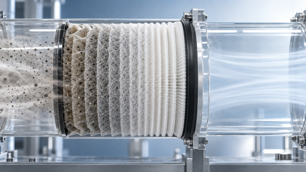
Pleated media relies on open channels between pleats. When pleats touch each other, collapse, or become packed with dirt at their base, the available airflow area falls sharply. This is sometimes mistaken for “dirty media,” but the underlying cause may be unsuitable pleat spacing, inadequate support, excessive airflow, moisture exposure, or aggressive pulse cleaning.
Check for bent end caps, damaged inner liners, softened adhesive, and pleats that have shifted toward one another. If the outer surface seems only moderately dirty but the pressure drop is severe, blocked pleat channels are a likely explanation.
What the pressure-drop pattern usually tells you
Do not use cleaning as the default response
When airflow falls, it is tempting to clean the element with compressed air. That can be appropriate only when the filter design and maintenance instructions allow it. It is not a universal fix.
High-pressure air can damage fine fibers, enlarge weak spots, separate layers, or force embedded dirt deeper into the structure. A filter may appear cleaner while retaining high resistance or allowing more particle passage. Washing can create similar problems when the media, adhesive system, or support layers are not intended for wet cleaning.
Replacement is usually the more reliable choice when the media is wet, oil-coated, hardened, torn, visibly collapsed, or heavily loaded through the depth of the material. Cleaning should not be used to extend service life beyond the condition where the element can still provide predictable filtration and airflow.
Match the media to the contamination, not only the equipment model
Two machines with the same filter housing can need different media solutions. The correct choice depends on airflow demand, particle size distribution, dust concentration, moisture, vibration, service interval, and the consequences of insufficient air supply. A construction machine working on dry soil faces a different loading pattern from one operating around cement dust, wet aggregate, or oily industrial emissions.
For construction machinery intake filtration, the element should be assessed as a system: the pre-cleaner or inlet arrangement, the primary filter, the secondary protection stage where fitted, the housing seal, and the maintenance practice all affect restriction. A media upgrade cannot compensate for a poorly sealed airbox or an intake that repeatedly draws in water and coarse debris.
When reviewing a material option such as GF0907 for construction machinery intake filtration, begin with the operating environment and element design. Confirm that the media construction is intended for the required airflow and service conditions, then evaluate how it behaves with the actual dust and moisture exposure. The useful question is not whether a material is “high performance” in general, but whether it maintains a workable balance between contaminant retention and airflow in that intake system.
A practical isolation check before changing the specification
If equipment condition allows, use a controlled comparison rather than guessing. Record the differential pressure with the existing element at a known operating condition. Inspect the housing and intake path. Then install a correct, clean comparison element and repeat the measurement under as similar a condition as possible.
If the pressure drop returns to normal, retain the removed element for inspection. Note whether its loading is uniform, whether the pleats remain open, and whether contamination is dry, sticky, wet, or unusually fine. This information is more valuable than simply recording that the filter was “dirty.” It indicates whether the next action should be a normal replacement, a change in maintenance timing, an upstream intake correction, or a different Air Filter Media construction.
If the reading remains high with a clean, correct element, stop changing media. The restriction is likely elsewhere in the air path, or the system is being operated at a condition beyond the original airflow assumption.
Common judgments that lead to the wrong fix
- “The filter is clean, so it cannot be restrictive.” Fine particles and oil-related deposits can block pore paths without producing a dramatic visible dust cake.
- “Higher efficiency always means better protection.” It can create unnecessary resistance when the equipment does not need that level of capture or when the element lacks sufficient media area.
- “A larger pressure drop proves the filter is working well.” Restriction only shows resistance to airflow. It does not prove sealing quality, media integrity, or suitable filtration performance.
- “Replacing the filter solves the cause.” A new element can temporarily restore airflow while water ingress, oil contamination, excessive dust exposure, or a collapsed inlet component continues to create the same failure pattern.
The most reliable diagnosis combines measurement, inspection, and operating context. Confirm that the pressure loss is truly across the filter, examine how the media has loaded or deformed, and compare the result with a clean, correct element at similar airflow. That process identifies whether the appropriate action is replacing a spent filter, correcting an upstream problem, or selecting a media design better suited to the real conditions.
Recommendation
 Oct 10, 2026
How Can Air Filter Media Increase Dust Holding Capacity Without Higher Pressure Drop?
Which liquid filter media is suitable for hydraulic oil fine-particle filtration? Discover how advanced air filter media increases dust holding capacity with low pressure drop.- Oct 10, 2026
Which Liquid Filter Media Is Suitable for Fine Hydraulic Oil Filtration?
Can synthetic filter media replace glass fiber in high-humidity gas turbine intakes? Explore media choices for fine hydraulic oil filtration, balancing efficiency, moisture resistance, pressure drop, and service life. - Oct 10, 2026
Can Synthetic Filter Media Replace Glass Fiber in Humid Turbine Intakes?
Is ePTFE filter media suitable for pulse-cleaned construction equipment air filters? Explore synthetic vs. glass fiber performance in humid turbine intakes.