



What causes early fouling in gas turbine intake filter media
What Causes Early Fouling in Gas Turbine Intake Filter Media?
Early fouling in Gas Turbine Intake Filter Media can quickly turn a routine maintenance task into an operational concern. A filter that loads too fast raises differential pressure, restricts intake airflow, and may force an unplanned change-out before the expected service interval. For aftermarket maintenance personnel, the immediate question is often, “Why did this filter plug so early?” The more useful question is, “What combination of site conditions, filter design, and maintenance practices caused the loading pattern?”
Premature fouling is rarely caused by one factor alone. A dusty environment may be manageable with the correct prefiltration stage; humidity may be harmless until it combines with fine dust; oil mist may not create high particulate loading by itself, but it can make ordinary dust adhere permanently to the media. Understanding these interactions is the practical route to protecting turbine airflow and avoiding repeated, expensive filter replacements.
Early Fouling Is Not Always the Same as High Dust Loading
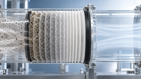
A filter can reach an unacceptable pressure drop for several different reasons. In one case, the media may simply be holding the amount of dust expected from a heavily contaminated environment. In another, the surface may be blinded by a thin sticky layer that prevents air from passing through the remaining open structure. These conditions look different during inspection and require different corrective actions.
Maintenance teams should avoid treating every plugged filter as a “dust problem.” Look closely at the removed elements. Is the contamination dry and loose, damp and crusted, oily and dark, or concentrated near the inlet face? Does it appear evenly across the filter bank, or is it much worse on one side of the housing? The physical appearance of the fouling often points toward the root cause faster than a generic replacement schedule does.
Dry particulate overload
Construction work, quarrying, unpaved roads, mining activity, agricultural operations, and seasonal dust storms can introduce a large mass of coarse and fine particles into the intake system. If the inlet is positioned too close to the ground, vehicle traffic, material handling areas, or a dust-generating process, the filters may accumulate contaminant far faster than their design basis assumed.
Dry loading is usually distributed over a broad area of the media, although poor inlet airflow can create local hot spots. In this situation, the solution may involve improving inlet location, adding or upgrading weather hoods and pre-separators, reviewing pulse-cleaning performance where applicable, or selecting media with a better balance between dust-holding capacity and initial pressure drop.
Surface blinding by fine particles
Fine dust is often more troublesome than visibly heavy dust. Cement dust, fly ash, carbon black, soot, metal oxide fines, and very fine mineral particles can form a compact layer on the upstream surface of Gas Turbine Intake Filter Media. Once this “dust cake” becomes dense, airflow resistance rises sharply even if the total captured mass does not appear unusually high.
This problem becomes more severe when a filter relies on depth loading but is exposed to a large fraction of submicron or highly cohesive particles. A media structure that works well for coarse outdoor dust may not behave the same way near industrial emissions, port facilities, refineries, or combustion sources. For fine-particle environments, a surface-layer strategy, appropriate efficiency grade, and sufficient media area should be considered together rather than independently.
Moisture Changes the Way Contaminants Behave
Humidity alone does not automatically foul a filter. The problem begins when moisture enters the intake in droplets, mist, condensation, or repeated wet-dry cycles. Dust that would normally remain loose can become adhesive when wet. As it dries, it may harden into a crust that is difficult to remove and that permanently blocks pores in the media.
Common sources include rain penetration through damaged louvers, inadequate weather protection, fog events, evaporative cooling systems, leaking wash-water systems, and condensation within ductwork. Coastal and tropical sites face additional challenges because wet particles may contain dissolved salts that remain on the media after the water evaporates.
A useful inspection clue is uneven wetting. If filters near the bottom of the bank, near housing seams, or directly behind louvers foul much earlier than other positions, water ingress should be investigated before changing the filter specification. Check drainage paths, seals, access doors, hood geometry, and whether moisture separators are installed and functioning as intended.
Wet-dry cycling and hardened deposits
Many maintenance teams are familiar with filters that look acceptable after a dry season but suddenly show a steep pressure-drop increase during periods of fog or intermittent rain. This is often a wet-dry cycling issue. Fine particles settle into the media surface, absorb moisture, then bind together as conditions change. The resulting deposit can have very different airflow resistance from the original loose dust.
In these conditions, water-resistant treatment, suitable binder chemistry, and media stability matter. The material must retain its structure without becoming vulnerable to swelling, fiber release, or loss of pleat geometry. However, a water-resistant medium cannot compensate for direct water carryover caused by a failed inlet protection system.
Oil Mist Can Turn a Normal Filter into a Sticky Collector
Oil aerosols are among the most common reasons for unexpectedly rapid fouling in industrial turbine installations. They may originate from nearby compressors, crankcase vents, lubrication systems, hydraulic equipment, process vents, vehicle exhaust, or other plant operations. Even a small amount of oil can create a tacky film on the intake-side surface. Once that film is present, ordinary dust no longer sheds or distributes normally; it sticks.
Dark, greasy, or unevenly stained filter surfaces are warning signs. The pressure drop may rise quickly despite a relatively light visible dust layer because oil can coat the fibers and narrow the air passages. In severe cases, deposits can migrate deeper into the media, making cleaning ineffective or unsafe.
Root-cause work should extend beyond the turbine enclosure. Walk the area around the intake during normal operation and during transient events. Check for vents that discharge toward the inlet, maintenance practices that create airborne lubricant mist, and changes in nearby production activities. A filter change may restore airflow temporarily, but it will not solve recurring oil aerosol exposure.
Salt Aerosols and Corrosive Atmospheric Contaminants
Coastal, offshore, and marine-adjacent gas turbine sites require special attention. Salt aerosols are often small enough to penetrate deep into an intake system, particularly during high winds, sea fog, or storms. They can combine with moisture and fine dust to form deposits that are both restrictive and corrosive.
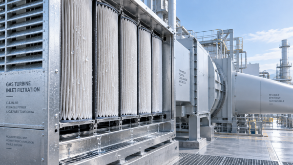
The concern is not limited to early fouling. Inadequate removal of salt-bearing aerosols can increase the risk of compressor fouling and corrosion downstream. For maintenance personnel, this means the filter system must be assessed as a complete barrier arrangement: weather hood, mist eliminator, prefilter, fine filter stage, housing integrity, gasket compression, and bypass control all influence actual protection.
Do not assume a filter with high particle efficiency automatically provides the best salt-management outcome. The selected configuration must suit droplet size, aerosol concentration, airflow velocity, local weather patterns, and the turbine manufacturer’s intake requirements. Excessive face velocity through the final stage can undermine an otherwise appropriate media choice.
When the Filter Media Is Not Matched to the Application
A media selection can be technically sound in one environment and unsuitable in another. Early fouling often appears after a site changes operating conditions without revisiting the intake filtration design. A turbine originally installed in a relatively clean area may later be exposed to construction, added road traffic, new process exhausts, or a different seasonal operating profile.
Key selection questions include:
- What particle sizes dominate at the site: coarse dust, fine industrial particulate, soot, salt aerosol, or mixed contamination?
- Is the exposure primarily dry, humid, oily, corrosive, or subject to sudden weather events?
- Does the existing media provide adequate dust-holding capacity at the required filtration efficiency?
- Is the filter construction stable under moisture, temperature variation, and mechanical vibration?
- Are pleat spacing, media area, and pack design appropriate for the system’s airflow and face velocity?
Media chemistry and processing also affect long-term behavior. Functional filtration materials may use different fiber blends, resin systems, lamination methods, and surface treatments to achieve particular properties such as water resistance, flame-retardant behavior, stiffness, or compatibility with a specified forming process. The right choice is not simply the most efficient sheet; it is the material that maintains predictable airflow and contaminant control under real operating conditions.
Manufacturers with wet-laid synthetic, adhesive lamination, spray lamination, and ultrasonic bonding capabilities can tailor material structures for demanding filtration applications. This broader materials perspective is valuable when standard media repeatedly fails to meet the contamination profile of a particular site.
Installation Errors That Mimic a Media Failure
Before concluding that the Gas Turbine Intake Filter Media is defective, inspect the installation. A missing gasket, distorted frame, damaged seal, improperly seated cartridge, or warped access door can allow bypass air to enter. Bypass itself may not always cause early filter plugging, but it can create unusual airflow distribution. Some sections of the filter bank then receive a disproportionate share of the flow and foul earlier than others.
Incorrect orientation is another avoidable issue. Certain filter designs depend on the correct upstream/downstream placement, drainage direction, and support arrangement. If pleats are compressed, spacers are damaged, or elements are forced into an opening that does not fit properly, the available filtration area can be reduced.
Record the location of every failed element during replacement. A map of pressure-drop problems across the bank can reveal inlet turbulence, water entry, leakage, or a localized contamination source. Replacing all elements without documenting their positions removes evidence that may be crucial to resolving the underlying issue.
Maintenance Practices That Shorten Service Life
Some premature failures begin after the filters arrive on site. Media can be damaged by poor storage conditions, especially in humid warehouses or areas exposed to dust, chemicals, and direct sunlight. Filter packs should remain sealed until installation, stored off the floor, and protected from crushing or moisture.
Another frequent issue is relying on calendar-based replacement alone. A time interval is useful for planning, but differential pressure and visual inspection provide a better picture of actual loading. Replacing filters too late risks airflow restriction; replacing them too early wastes usable service life and can conceal a progressive contamination problem.
Attempts to clean disposable or non-cleanable elements can also cause trouble. Compressed air may drive particles deeper into the media, damage fibers, open weak points, or disturb surface treatments. Unless the filter manufacturer explicitly approves a cleaning method for a specific design, replacement is generally the safer approach.
A Practical Investigation Sequence for Aftermarket Teams
When filters foul early, begin with evidence rather than assumptions. Compare the current pressure-drop trend with historical data, noting weather events, nearby work, operational changes, and wash cycles. Inspect the removed filters for dry dust, oil, salt residue, moisture marks, or localized loading. Then examine the intake housing, louvers, drainage, seals, and airflow path.
It is also helpful to separate immediate containment from long-term correction. The immediate task may be replacing loaded elements and restoring airflow. The long-term task may involve modifying inlet protection, changing maintenance intervals, eliminating an oil-mist source, or qualifying a more suitable media construction.
Material expertise developed for adjacent filtration sectors can support this evaluation. For example, OS320500 is a cellulose-based and cellulose/synthetic material platform developed for liquid filtration applications, including transmission oil filtration, where removal of carbon residue and metal particles is important. Its available acrylic and phenolic resin options illustrate why binder selection and resistance properties must be evaluated carefully in any filtration design. The material itself is intended for liquid filtration rather than turbine intake duty, but the engineering principle is relevant: contamination type, media structure, and binder behavior must be matched to the operating environment.
What Good Filter Life Looks Like
A healthy intake filtration system does not necessarily mean the filters remain visually clean. Filters are expected to capture contaminants. What matters is whether pressure drop rises at a predictable rate, loading is reasonably uniform, seals remain intact, and the turbine receives the airflow and protection required for stable operation.
When early fouling occurs repeatedly, treat it as operating data rather than bad luck. The removed media is telling a story about the air entering the turbine. By identifying whether that story involves fine dust, water, oil mist, salt, unsuitable media, or airflow imbalance, maintenance teams can move from repeated replacement to a more durable and controlled intake filtration strategy.
Recommendation
 Oct 10, 2026
How Can Air Filter Media Increase Dust Holding Capacity Without Higher Pressure Drop?
Which liquid filter media is suitable for hydraulic oil fine-particle filtration? Discover how advanced air filter media increases dust holding capacity with low pressure drop.- Oct 10, 2026
Which Liquid Filter Media Is Suitable for Fine Hydraulic Oil Filtration?
Can synthetic filter media replace glass fiber in high-humidity gas turbine intakes? Explore media choices for fine hydraulic oil filtration, balancing efficiency, moisture resistance, pressure drop, and service life. - Oct 10, 2026
Can Synthetic Filter Media Replace Glass Fiber in Humid Turbine Intakes?
Is ePTFE filter media suitable for pulse-cleaned construction equipment air filters? Explore synthetic vs. glass fiber performance in humid turbine intakes.