



Can ultrasonic lamination preserve filter media air permeability?
Yes—Ultrasonic Lamination can preserve much of a filter medium’s air permeability when it creates small, controlled bonds and leaves the surrounding pore structure open. The outcome depends on the materials, bond pattern, and processing conditions. Removing adhesive does not automatically produce a breathable composite: excessive compression or melting can restrict airflow even when no adhesive is present.
A useful assessment therefore considers three results together: airflow resistance, filtration performance, and interlayer strength. A laminate that breathes well but separates during pleating is unsuitable. So is a strong laminate whose bonding process damages the filtration layer. The objective is a stable composite that meets all three requirements under its intended operating conditions.
Why localized bonding can help preserve airflow
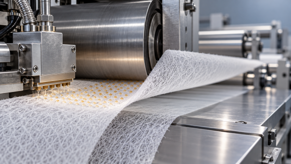
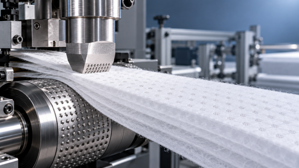
Ultrasonic lamination uses high-frequency mechanical vibration, applied through a horn against an anvil, to generate heat locally within a material stack. Compatible thermoplastic components soften and form bonds under pressure. With a patterned anvil, these bonds can be concentrated into selected points or lines rather than spread across the entire surface.
This leaves areas between the bonds available for airflow. It can also avoid adhesive migration into pores, which may occur when an adhesive’s application pattern, viscosity, or coating weight is poorly matched to the media.
However, adhesive lamination does not necessarily create a continuous barrier. Controlled dots, webs, or other discontinuous adhesive patterns can also maintain open flow paths. The relevant comparison is between workable constructions using the same functional layers—not between ultrasonic bonding and an assumed solid film of adhesive.
Bonded areas generally offer greater airflow resistance than the surrounding porous media. Air redistributes through the remaining open regions, potentially increasing local velocity there. Consequently, the percentage of visibly unbonded surface does not directly predict retained permeability. Compression around each bond, changes in thickness, and the resistance of the individual layers also affect the result.
Material compatibility determines whether the process is viable
Before adjusting machine settings, establish which component will form the bond. A thermoplastic support, bicomponent fiber, or suitable meltable layer may provide the bonding phase. The presence of synthetic fibers alone is insufficient: polymers differ in their softening behavior, acoustic response, and ability to bond to neighboring materials.
A cellulose-rich sheet, for example, does not melt like a thermoplastic web. It may require a compatible thermoplastic component or another bonding approach. Likewise, two layers that each respond to ultrasonic energy may still form a weak interface if their polymers are incompatible or the meltable component cannot reach the contact surface.
Layer arrangement matters just as much as composition. A robust support might tolerate the process while an adjacent fine-fiber layer suffers localized collapse or tearing. Thin membranes and delicate coatings deserve particular attention because damage can increase airflow while reducing particle retention. A higher permeability reading can sometimes indicate a defect rather than an improvement.
Material specifications also need to be interpreted in their application context. For example, OS320500 is an oil-filtration material offered in cellulose, cellulose/synthetic, and cellulose/synthetic/PBT constructions, with acrylic non-cured and phenolic cured resin options. These descriptions identify relevant composition and resin choices; they do not establish ultrasonic weldability. A liquid-filtration material also requires evaluation using the intended fluid and operating conditions, even if air permeability is used as a manufacturing comparison.
For any candidate stack, obtain the layer construction, polymer types, resin or coating condition, thickness, and basis-weight tolerances. Those details help determine whether a useful bonding window is likely to exist.
The bond pattern must balance open area and mechanical support
A low bonded-area fraction is a reasonable starting point when airflow is sensitive, but reducing bond coverage indefinitely creates other problems. Layers can lift, wrinkle, or shift between widely spaced bonds. During pleating, unsupported regions may buckle differently, producing inconsistent geometry or separation.
Bond spacing and shape therefore matter alongside total coverage. Small, distributed points can provide support while leaving open regions. Lines may provide directional reinforcement, but their orientation can affect bending behavior and concentrate stiffness along a pleat. Broad bonded regions can create local restrictions that a simple average coverage value fails to describe.
The nominal anvil pattern is only part of the picture. Actual bonds can spread beyond the intended contact area if energy or pressure is excessive. A pattern designed to be open may produce flattened zones around each weld. Inspecting the finished laminate reveals whether the effective affected area matches the tooling design.
Evaluate patterns against the converting process as well as the flat-sheet specification. Media that passes an initial peel check may behave differently after folding, cutting, or repeated flexing. Pleat-tip damage and separation at cut edges can disqualify an otherwise promising construction.
How process settings change permeability
Ultrasonic energy, mechanical loading, and exposure time interact. Their effects cannot be assessed reliably by treating each setting as an independent adjustment.
- Vibration amplitude: Insufficient amplitude may leave incomplete bonds. Excessive amplitude can produce aggressive melting or damage sensitive fibers.
- Nip force or working gap: Enough contact is needed to transmit energy and form a bond. Excessive compression can densify the media around the weld and reduce local porosity.
- Line speed: Speed changes the time available for energy transfer. A setting that works during a slow trial may produce weak bonds at production speed.
- Web tension and alignment: Uneven tension can stretch, wrinkle, or distort layers before bonding, creating inconsistent contact across the web.
The appropriate target is a usable process window: a range of conditions that produces adequate strength without unacceptable airflow loss or filtration damage. A single successful sample at one narrow setting offers little confidence if ordinary thickness variation causes the result to fail.
Across-width consistency also matters. Horn and anvil alignment, tooling condition, and differences in material thickness can produce strong bonds in one region and weak or overprocessed bonds elsewhere. Sampling only the center of the roll can miss these variations.
Measure permeability without confusing it with filter performance
Air permeability usually describes airflow through a defined sample area at a specified pressure difference. Pressure drop describes the resistance encountered at a specified airflow or face velocity. These measurements are related, but comparisons are meaningful only when the test conditions are consistent.
Record the exposed area, pressure difference or airflow, sample conditioning, and clamping method. For compressible materials, differences in fixture loading can alter the result. Edge leakage can also make a restrictive sample appear more permeable than it is.
Use three reference conditions where practical: the individual layers, the unbonded stack held in a representative arrangement, and the finished laminate. Comparing a composite only with its main filtration layer confuses the resistance added by the support with changes caused by bonding. The unbonded stack helps separate those effects, although its layer contact must be controlled for the comparison to be useful.
Measure pressure drop at the intended operating face velocity and, where relevant, across the expected flow range. A result from an unrelated test condition may not reflect the finished filter’s behavior. Compare samples from multiple web positions and from separate production intervals to assess consistency.
Airflow results must be accompanied by particle-retention or penetration testing appropriate to the application. Local holes or damaged fibers may have little effect on an average permeability measurement while allowing particles through. Inspect bond regions and adjacent material, because damage may occur around the weld boundary.
For an assembled filter, evaluate sealing and pleat geometry as well. Flat-sheet measurements cannot establish whether the finished element has bypass leakage, crowded pleats, or reduced effective filtration area.
A practical qualification sequence
Begin with acceptance criteria for the finished construction. Define allowable pressure drop at the operating airflow, required filtration performance, and interlayer strength sufficient for converting and service. Include relevant environmental exposure, such as humidity, temperature, or contact with process fluids.
Then structure trials so that each result answers a decision:
- Confirm that a bond can form without visible damage. Screen the proposed layer stack and identify a workable range of energy and compression before committing to production tooling.
- Compare a limited set of bond patterns. Assess coverage, spacing, airflow resistance, and the support needed during pleating. Avoid selecting a pattern solely because it gives the strongest peel result.
- Evaluate strength and airflow on matching samples. This shows the tradeoff directly and prevents results from different processing conditions being combined into a misleading conclusion.
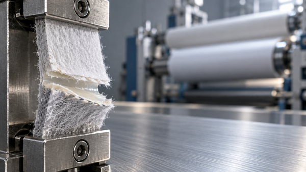
- Check filtration integrity and the failure mode. Distinguish separation at the interface from tearing within a layer. A strong interface can still be unsuitable if bonding has weakened the media beside it.
- Repeat after converting and relevant conditioning. Pleating, thermal exposure, humidity, or fluid contact may reveal weaknesses absent from fresh flat samples.
- Run at representative production conditions. Confirm that speed, web width, tension, and normal material variation remain within the accepted window.
Keep an approved reference sample and record both machine settings and material identification. When performance changes, this makes it easier to distinguish a process shift from a change in fiber blend, resin condition, or layer thickness.
When another lamination method may be the better choice
Ultrasonic bonding is a strong candidate when the stack contains compatible thermoplastic components, localized attachment provides sufficient support, and the sensitive filtration layer tolerates the process. It is less attractive when adequate bonding requires enough energy to damage that layer, or when the materials offer no reliable melt-bonding mechanism.
An adhesive process may provide a wider operating window for dissimilar materials or distribute attachment more gently across a fragile web. Its suitability depends on adhesive placement, add-on level, chemical compatibility, and service conditions. It still needs the same airflow and filtration validation.
Hangzhou Chaocai Materials Co., Ltd. has ultrasonic, PUR, hot-melt adhesive, and solvent-based emulsion spray lamination capabilities. For material development, access to different processes allows the bonding method to be evaluated against the construction’s requirements. The presence of an ultrasonic production line alone does not determine which route will deliver the required balance.
The next useful step is to specify the proposed layer stack and operating conditions, then request comparative samples with documented bond patterns and processing conditions. Select the construction that retains acceptable airflow and filtration efficiency while surviving conversion and service. That evidence establishes whether ultrasonic lamination preserves permeability well enough for the filter being designed.
Recommendation
 Oct 26, 2026
Why insufficient curing causes delamination in PUR lamination
PUR Lamination can delaminate when cooling masks incomplete cure. Discover how moisture, temperature, and bond testing help prevent failures and improve laminate reliability.- Oct 26, 2026
How adhesive coat weight affects hot melt adhesive lamination
Hot Melt Adhesive Lamination: learn how to optimize coat weight for reliable bonds, airflow and flexibility. Explore practical testing tips to reduce waste and improve filtration laminate performance. - Oct 26, 2026
Can ultrasonic lamination preserve filter media air permeability?
Can Ultrasonic Lamination preserve filter media airflow? Discover how materials, bond patterns, and process settings help balance permeability, filtration performance, and bond strength.